|
Barry Bogs--The Gauge 3 Steam Locomotives
|
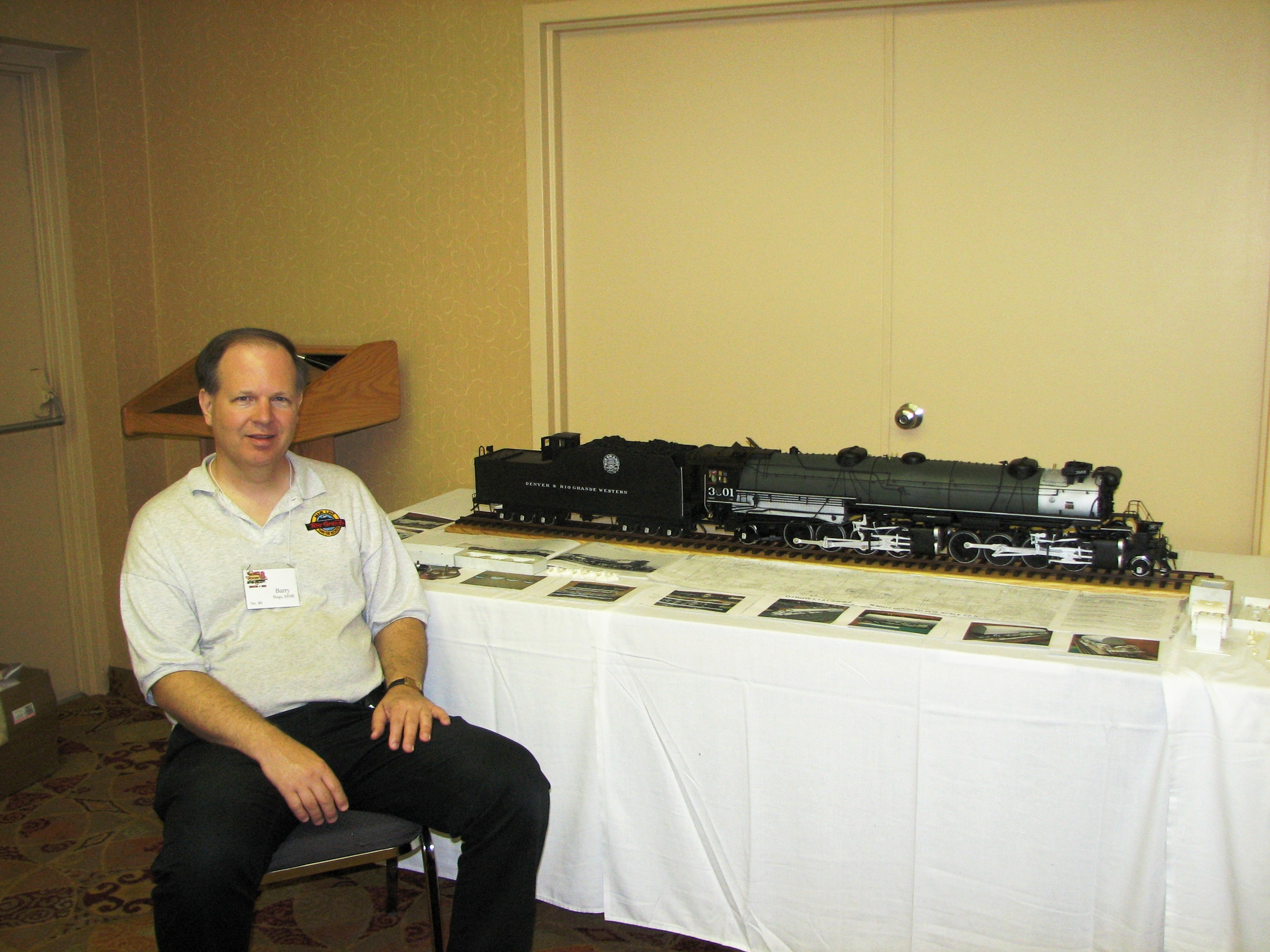
Barry Bogs is a prolific model builder residing in the
Houston, Texas area, whose work has appeared several times
over in
Model Railroader,
Garden Railways,
Finescale Railroader, and the LGB
Telegraph. In real life Barry is a technician for
Pitney-Bowes; but in his off time, He models the Denver &
Rio Grande Western in 1:22.5 scale, with both standard gauge
and narrow gauge operations, much like the prototype. Barry
uses Gauge 3 (2.5" between the rails) to represent 4'-8˝"
standard gauge and Gauge 1 to represent 3' narrow
gauge (what some are dubbing G and Gn3).
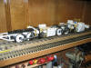
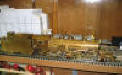
Barry's large scale indoor railroad, the
Colorado & Western, is
now in its second incarnation and covers nearly the entire
second floor, including the open foyer, of his substantial
home. But aside from Barry's layout being itself visually
stunning (as it tunnels through walls and crosses hallways
via lift-out bridges), his most impressive talent is his
scratchbuilt locomotives and
rolling stock. Only Barry's
standard gauge steam is presented here,
diesels here. Please see the
Colorado & Western site
for pics of Barry's layout and his stable of D&RGW narrow
gauge locomotives. Barry may be contacted at
blbogs@yahoo.com
|
Barry & Gauge 3--An Apology of
Sorts
Although Barry is not modeling in 1:20.3 standard
gauge (he has far too large an investment in 1:22.5 scale to even
think of switching), his work warrants a page on this website because (1) the Gauge 3 models he
builds are themselves very close in size and concept to 1:20.3
standard gauge, (2) the
techniques he uses are readily adaptable to standard gauge modeling
in 1:20.3, (3) he has completed a number of my former Gauge 3 projects, (3) he's
my friend, and (4) in some small measure I am responsible for getting
him started in Gauge 3. Perhaps a personal anecdote to that effect is in order
here.
Barry and I first met sometime in the early 90s while
I was still in seminary, unmarried, and just beginning to dabble in
Gauge 3. As has often been the case in the world of large scale,
Marc Horovitz was the facilitator who introduced Barry to myself,
having related to him that at least one other person was fiddling
with two rail electric models in Gauge 3 but residing nearly a 1000
miles away in east Tennessee. Sometime after that, Barry visited me
between semesters at my parents home in
Knoxville where I had set up a workshop with a 24' long shelf
layout for testing
purposes. Those two
tracks, with their #8 crossover, the as-of-then incomplete
Canadia City Boxcar and
40' basswood
flat, were probably the first Gauge 3 models Barry had seen
in person, though he had seen photos of the hard-to-find
Magnus products. He was hooked.
Several years after this, Barry visited again, and I was able to
place a handful of custom-made Gauge 3 axles in his hands. Since
that time, he has adopted three of my Gauge 3 flat cars, completed an
orphaned 2-bay hopper, transformed a box of disparate parts into a
beautiful 2-4-4-2 mallet, built his own fleet of standard gauge
freight cars, and constructed the largest indoor dual gauge layout
in 1:22.5 scale in the country. Given his accomplishments, I'm now convinced either
Barry does not sleep, does not really have a day job and is in fact
independently wealthy, has a twin brother who also likes trains, or
perhaps some combination of all three. Whatever the case, you may
judge for yourself below.
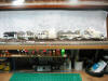
Tools & Techniques
.gif) Barry builds
his locomotives and rolling stock from a combination of styrene
plastic, urethane castings (made from his own styrene patterns), metal
detail parts, and where locomotives are concerned, LGB motor blocks
and wheelsets, regauged if necessary to Gauge 3. He is able to work
with incredible speed from--now get this--a roll top desk in his
family room! The actual urethane casting process, as well as the
painting of his models, is done in a non-air-conditioned garage (in
stiflingly hot and humid Houston) and out-of-doors, respectively. Barry builds
his locomotives and rolling stock from a combination of styrene
plastic, urethane castings (made from his own styrene patterns), metal
detail parts, and where locomotives are concerned, LGB motor blocks
and wheelsets, regauged if necessary to Gauge 3. He is able to work
with incredible speed from--now get this--a roll top desk in his
family room! The actual urethane casting process, as well as the
painting of his models, is done in a non-air-conditioned garage (in
stiflingly hot and humid Houston) and out-of-doors, respectively.
Because Barry's models are meant to run, and to run
reliably, they are constructed somewhere between museum quality and
semi-scale. For instance, since LGB provides the running gear almost
exclusively, a given steam locomotive wheelbase may be off by a few
scale inches, and Barry's typical wheelset is LGB off-the-shelf
with its tinplate style high flanges (but most visitors, at least
the polite ones, are not measuring his locomotives with a set of
dial calipers). Likewise, brake rigging mounted beneath a car or
locomotive is rarely duplicated because it is almost never seen and,
well, gets torn off with very much use or handling. Those items for
which no commercial parts are available (domes, cabs and such) Barry
scratch- builds, and
these parts do scale out on the money. Rivets for
instance follow the pattern of prototype drawings and number in the
hundreds for any given tender or freight car. What Barry has done,
then, is to achieve a workable balance between reliable operation
and proportional good looks.
 Since LGB
does not offer a plastic, Gauge 3 steam locomotive, Barry has had to
go beyond the techniques of the typical kitbasher to arrive at
something a little more radical, while still making use of a
commercially available drive. The result is what might best be
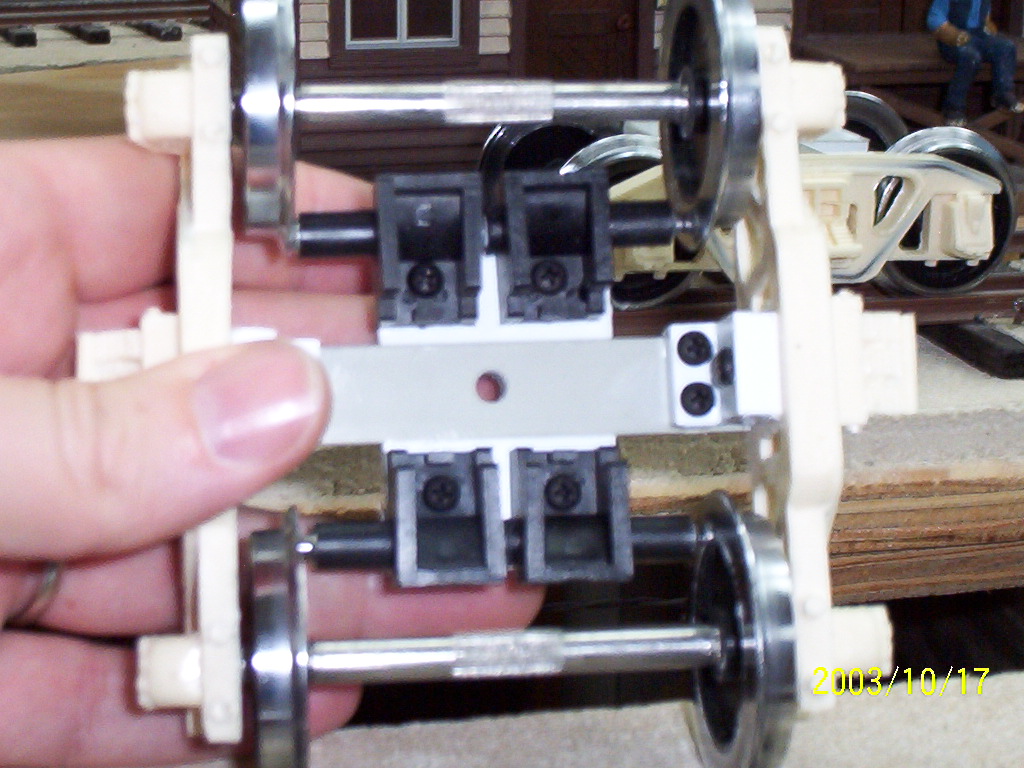
described as motor block sandwich. Simply put, an LGB
motor block, with either its own or more likely after-market drivers
of an appropriate OD, is regauged using new 6mm axles. A new styrene
frame to match that of the prototype locomotive is cut out, spacers
between it and the motor block are also cut, and the whole assembly
is glued and screwed together. No new axle bearings are provided for in
the sandwich; rather, the original motor block's own bearing surfaces
suffice. New cylinders, engine truck frames, and such are then
fabricated out of styrene and PVC tube and attached to the new
styrene frame. Generally, there is no working suspension: All leaf
springs, equalizers & levers are entirely aesthetic. Since LGB
does not offer a plastic, Gauge 3 steam locomotive, Barry has had to
go beyond the techniques of the typical kitbasher to arrive at
something a little more radical, while still making use of a
commercially available drive. The result is what might best be
described as motor block sandwich. Simply put, an LGB
motor block, with either its own or more likely after-market drivers
of an appropriate OD, is regauged using new 6mm axles. A new styrene
frame to match that of the prototype locomotive is cut out, spacers
between it and the motor block are also cut, and the whole assembly
is glued and screwed together. No new axle bearings are provided for in
the sandwich; rather, the original motor block's own bearing surfaces
suffice. New cylinders, engine truck frames, and such are then
fabricated out of styrene and PVC tube and attached to the new
styrene frame. Generally, there is no working suspension: All leaf
springs, equalizers & levers are entirely aesthetic.
On some locomotives, such as Barry's first Gauge 3
mallet (a Denver & Salt Lake 2-6-6-0) a three axle LGB motor block
was used and the same sandwiching technique carried out. On an
eight-coupled locomotive, such as Barry's D&RGW L-131 2-8-8-2 simple
articulated (now on the workbench) or his C-41 2-8-0, the relatively new LGB Mikado
motor block (which is actually engineered as a 2-4-4-2, having a
hinge between the #2 and #3 drivers) can be adapted just as readily.
The only limitation with the LGB motor blocks is (1)
wheelbase--unless one is willing to cut the motor blocks themselves
apart, change the placement of motors and gears as needed, and
re-glue the assembly together) and (2) driver OD. So far the largest
LGB driver readily available is that of the Mikado which measures
about 43" in 1:20.3 across the tread; the Mikado's wheelbase being
about 51" between the drivers as well. |
|
The Locomotives
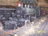
 Denver
& Salt Lake 2-6-6-0 Denver
& Salt Lake 2-6-6-0
(2004)
Built in 1916 by Alco's Schenectady
works for the Denver & Salt Lake, a line absorbed into the Denver &
Rio Grande Western in 1947, these 2-6-6-0 mallet compounds had 55"
drivers and exerted about 77,000 pounds tractive effort (hence the
D&RGW's designation L77). They were short lived on the
D&RGW, all of the class having been dismantled by mid 1952.
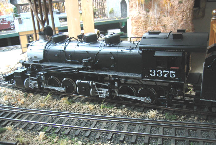
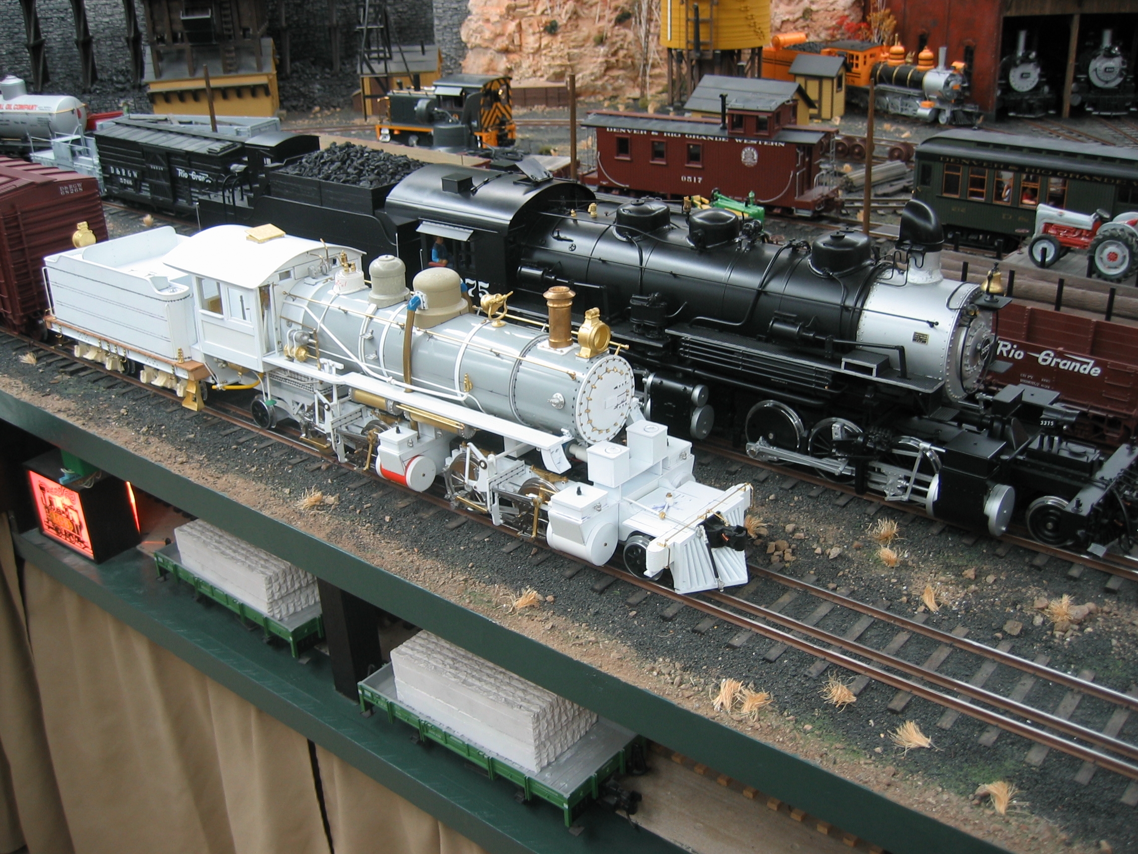
Barry's model of this unusual class of
mallet was intended mainly to demonstrate the startling difference
between a mid-size standard gauge mallet and the largest of 3'
narrow gauge equipment: the D&RGW outside frame K-37 2-8-2. It is
his first Gauge 3 locomotive, and his favorite so far. #3375 was
constructed with the help of an O scale
brass model imported by Pacific Fast Mail (PFM) and a handful of scale drawings provided by
the same. No readily available D&RGW or D&SL blueprints for this locomotive are
known to exist. |
|
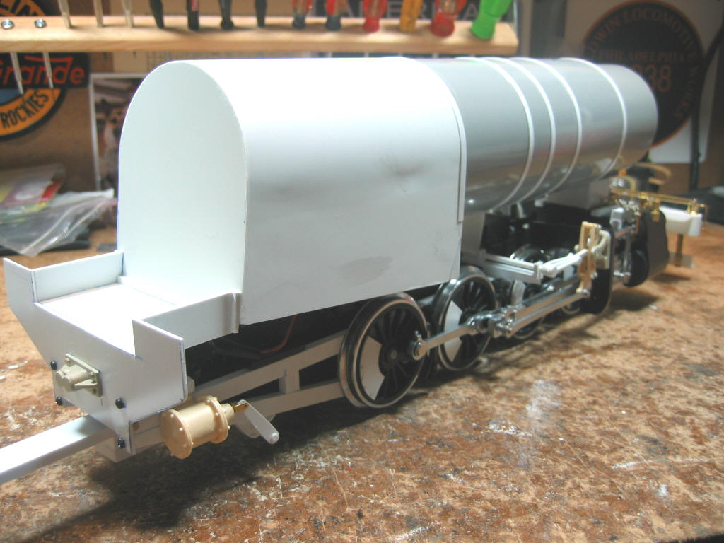
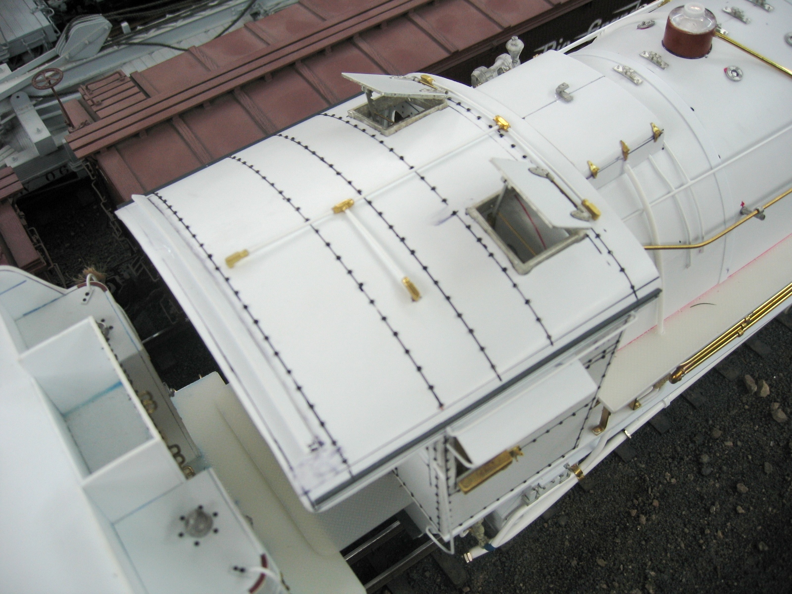
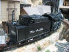
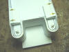
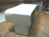
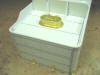
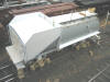
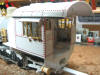
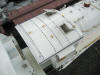
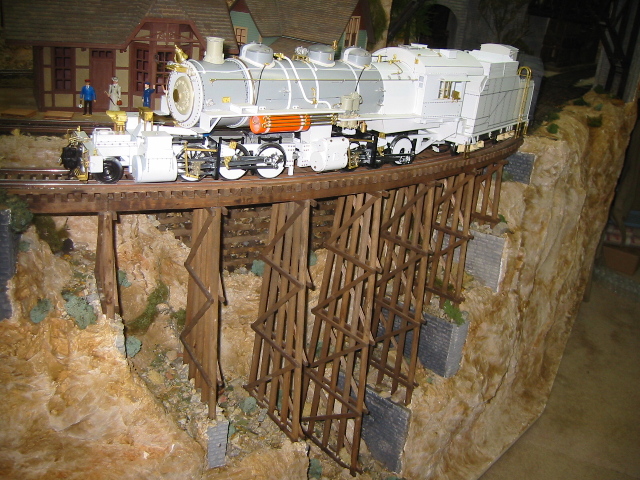
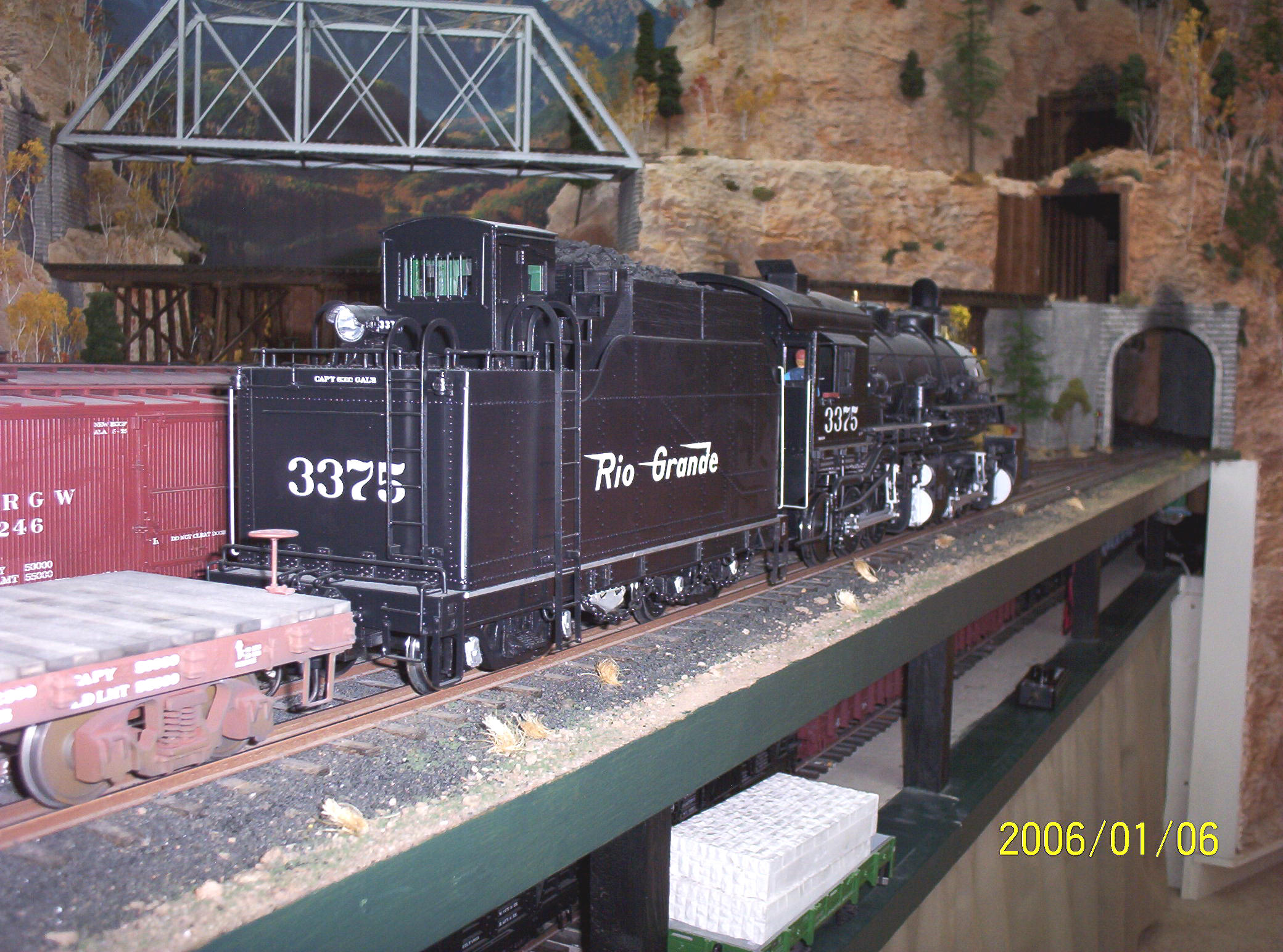
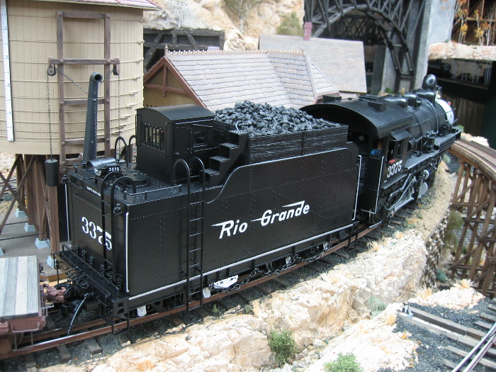
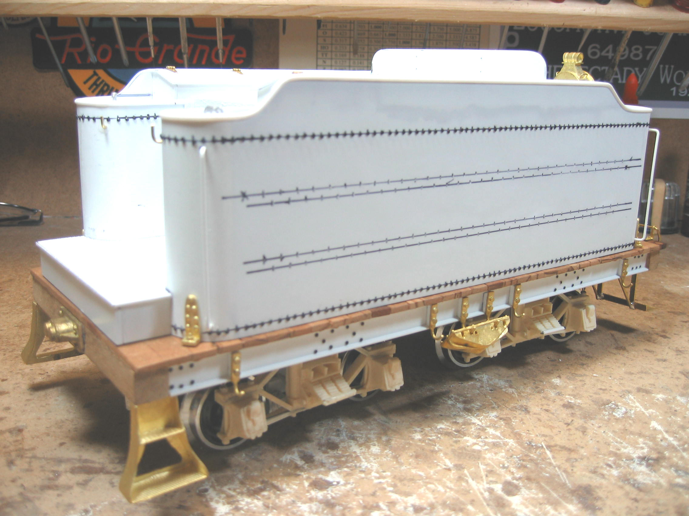
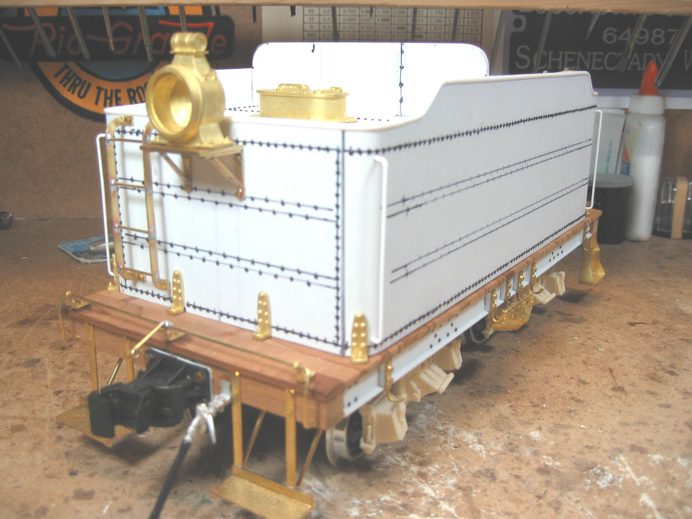
The Tender
The tender body, shown below, was made
from .060" styrene sheet, which was then wrapped in .010" sheet (in
order to mask the rounded corners made from sectioned lengths of PVC
pipe). Peco track nails were then applied to simulate rivets. The
tender underframe is made from Plastruct channels, and the whole
affair rides on cast urethane Andrews style tender trucks. LGB
plunger type wipers are used for power pickup. The trucks are rigid
since the high LGB tinplate flanges assure reliable operation on
undulating track.

 |
|
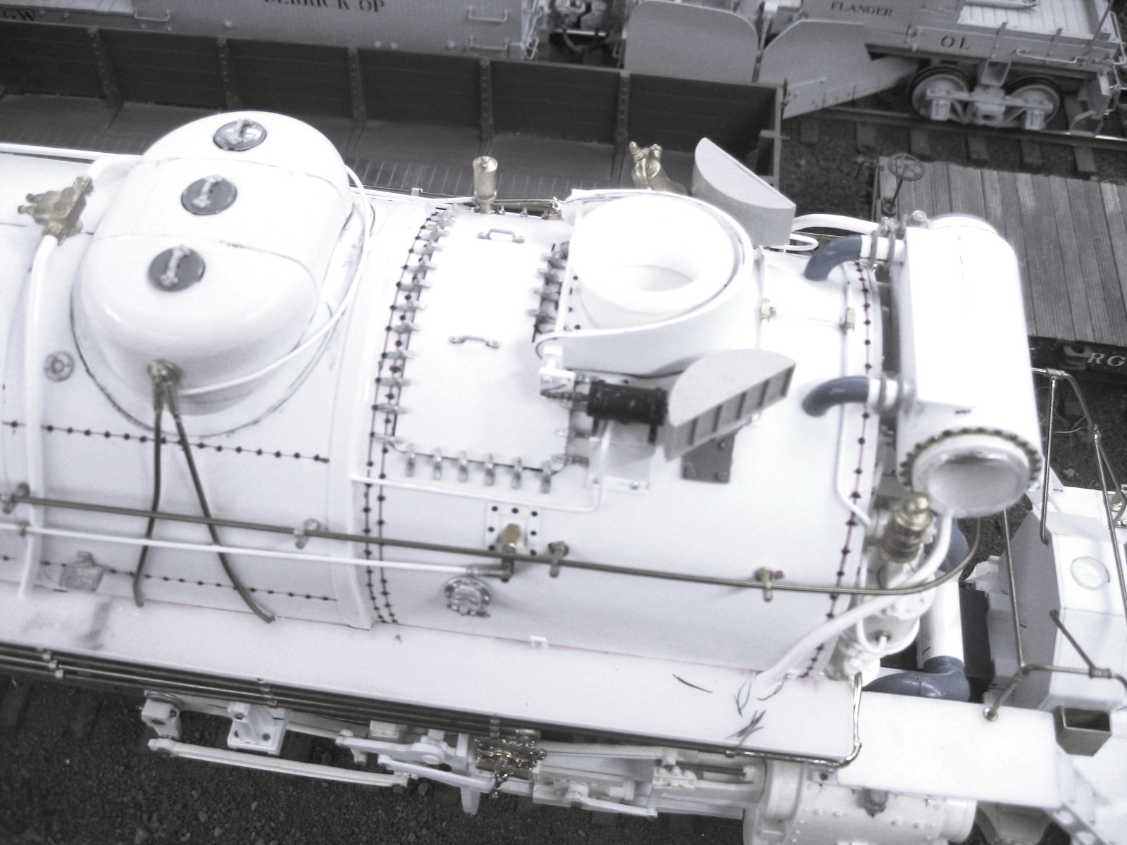
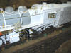
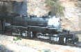
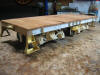
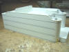
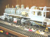
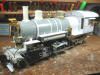
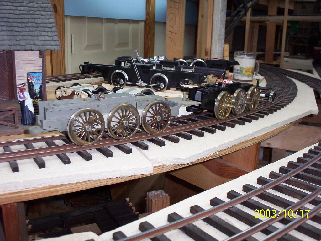
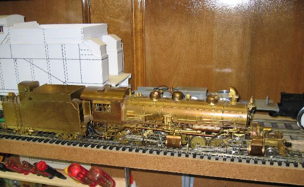
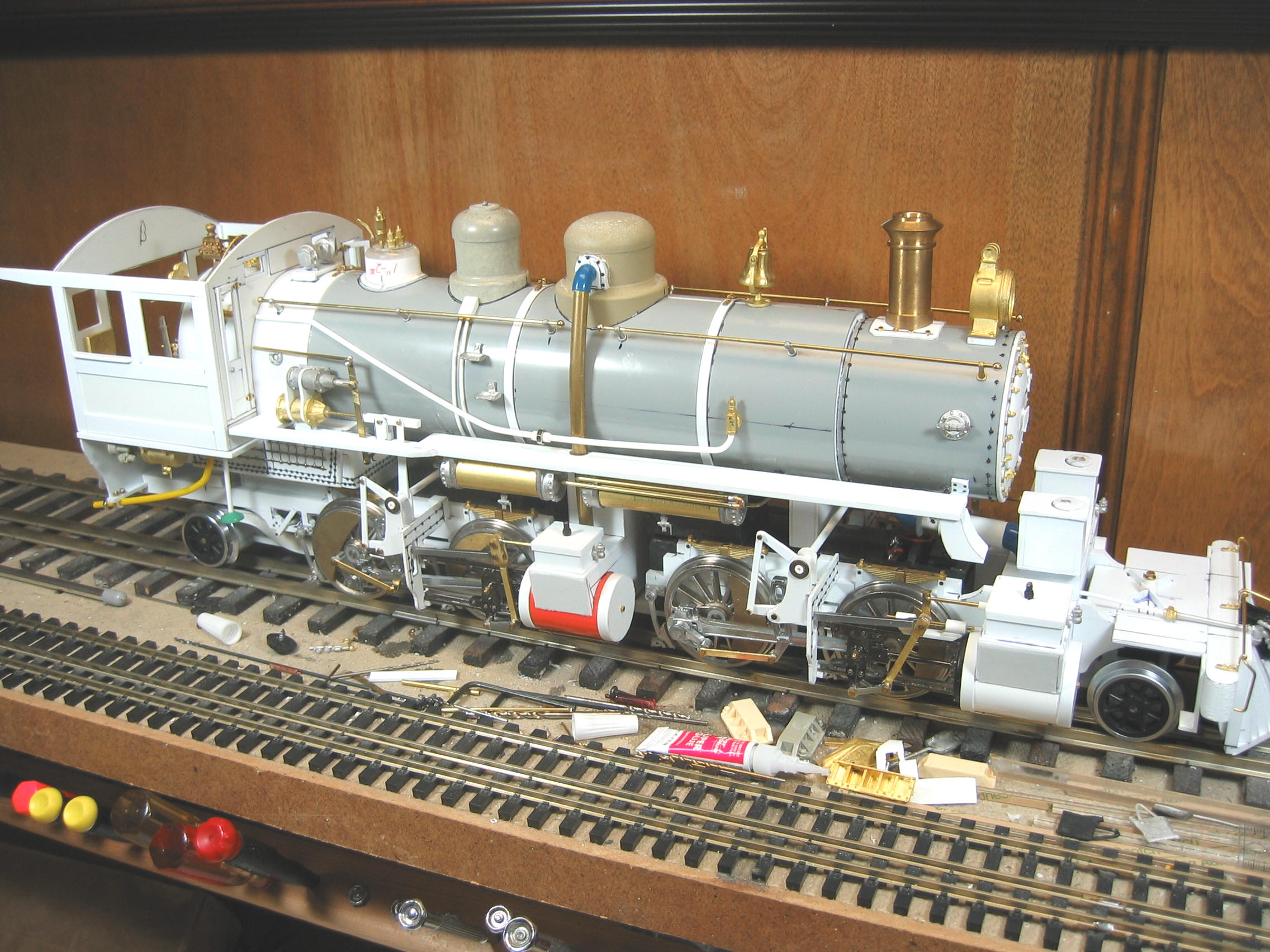
The Chassis, Boiler & Cab
Barry used two LGB Mogul motor blocks
for the #3375's drive, each regauged with new 6mm stainless steel
Gauge 3 axles and reequipped with LGB Mikado drivers (which were
themselves modified with new counterweights). The main frames
sandwiching the motor blocks are .250" thick Evergreen styrene
plastic strip. Similarly the tender and cab are made from .060"
styrene sheet. The boiler is a length of 4" OD Plastruct tube.
Cylinders and domes were fabricated whereas the stack was cast in
urethane from a styrene pattern. Three couplers are mounted to both
pilot and tender so as to facilitate dual gauge operation. The
locomotive is able to negotiate a 5' minimum radius curve.


 |
|
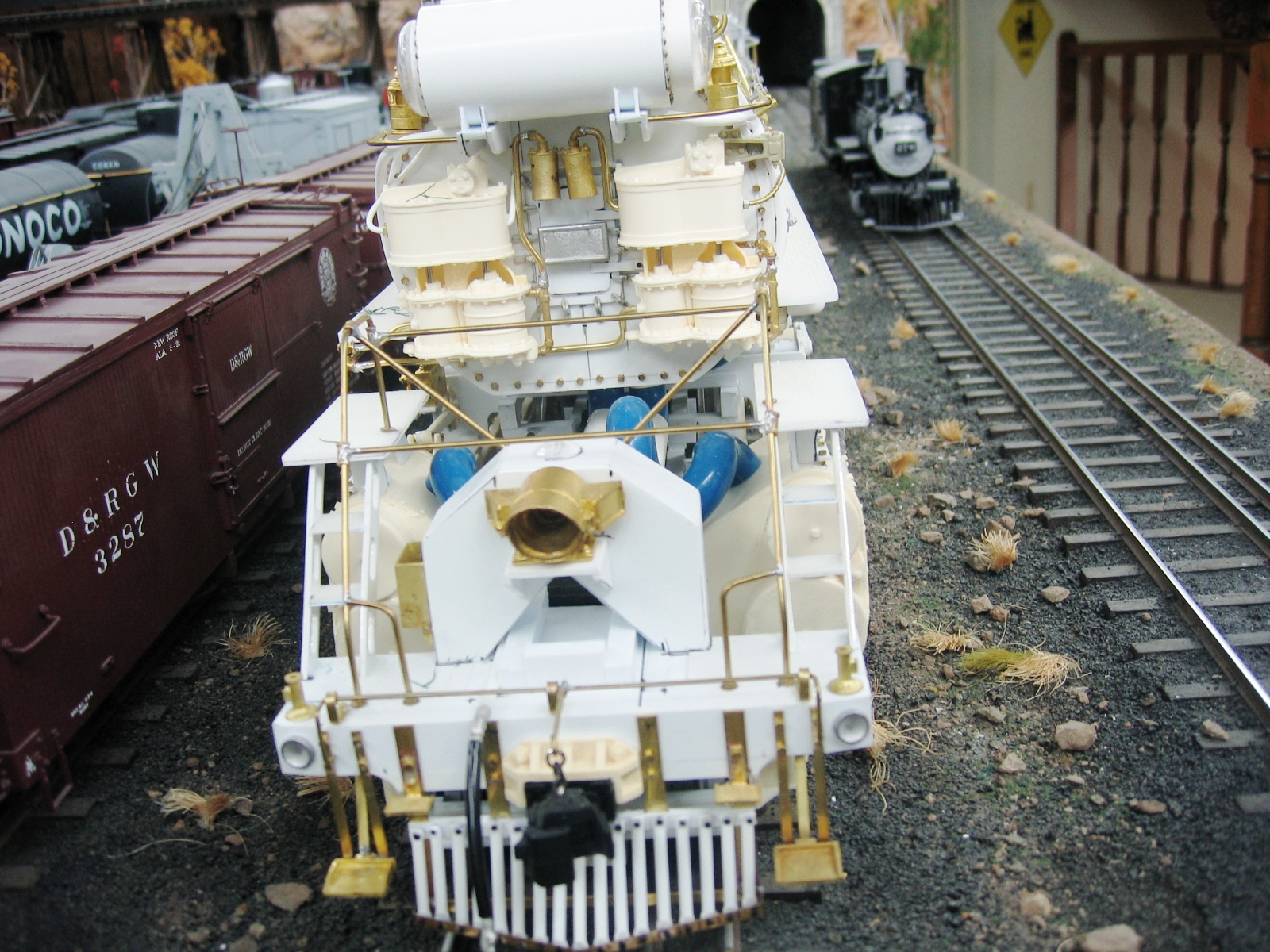
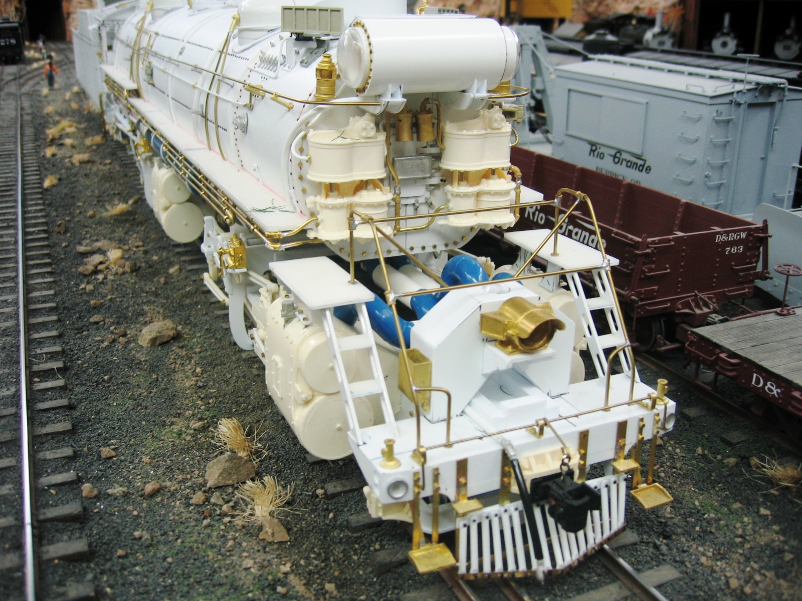
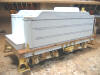
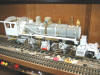
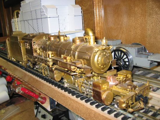
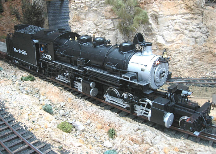
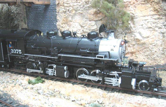
The Completed Locomotive


|
|
.jpg) Little River Railroad 2-4-4-2 Little River Railroad 2-4-4-2
(2005)
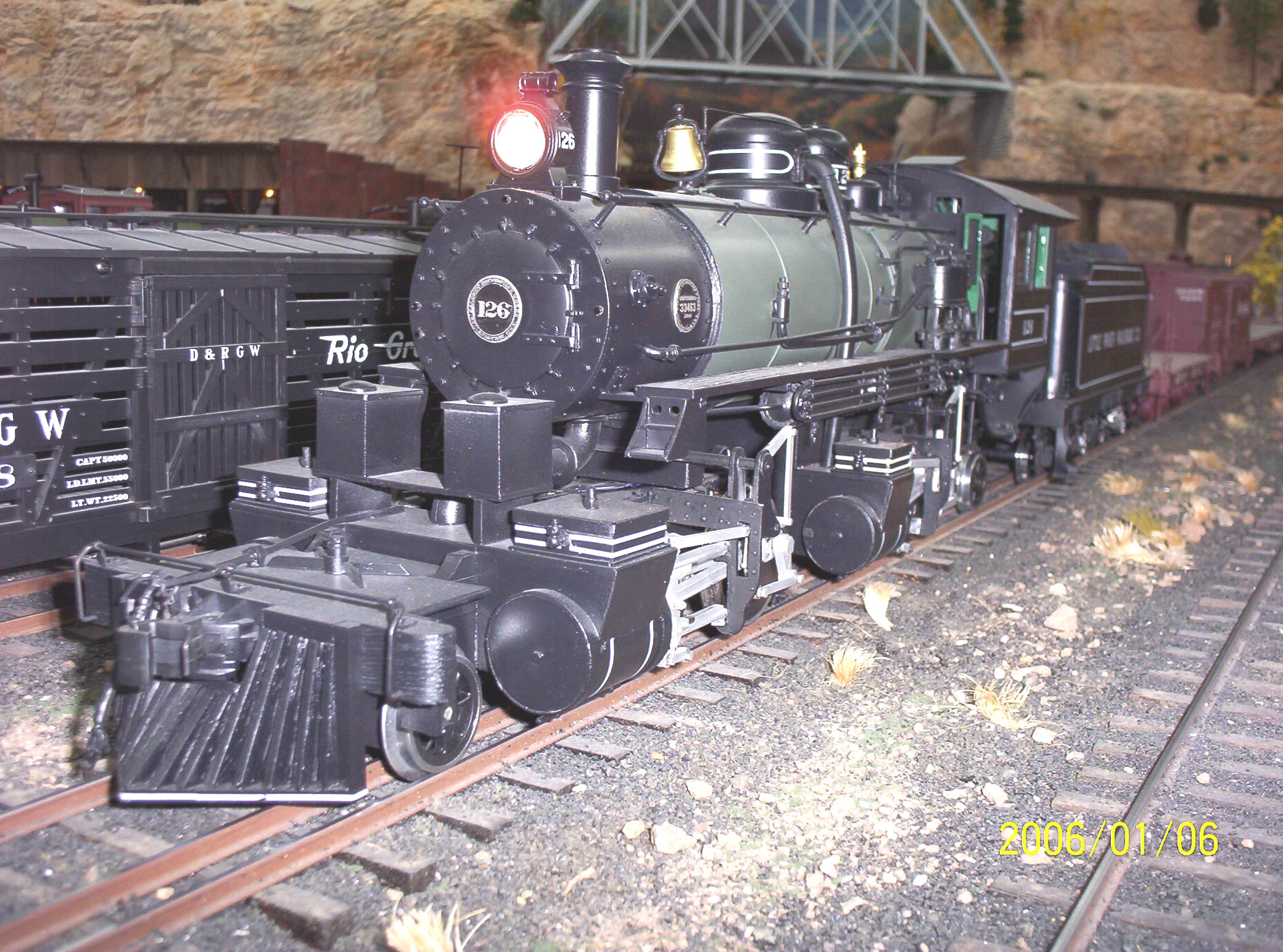
In the late Spring of 2005 Barry
visited my workshop here in East Tennessee where we discussed our
current and past projects. One of my past projects, from the Gauge 3
phase of my sojourn in large scale, was a series of Little River
Railroad logging mallets, each based upon the first of the Little
River's two mallets: #126 (The story of that project can be read
here,
_small.jpg) _small.jpg) near
the bottom of the page). Barry left that evening with all the
remaining parts I had on hand for the 2nd of
what would have been four locomotives, which included regauged
Palacina Productions drivers, spoked lead & trailing truck wheels
(adapted from an LGB electric locomotive), the tender underframe, an incomplete tender body,
Barry's own K-37 archbar tender truck castings, a couple of LGB 0-4-0 motor blocks, a
brass smokestack, a bag of commercially available detail
parts--including custom made builders and number plates by Robert
Dustin--and photo copies of all the dimensioned drawings and
research I had been able to accumulate for Little River#126, better
known on the West Coast, and to the present day--since the locomotive still exists, albeit in pieces--by its Native American
name, the Skookum. near
the bottom of the page). Barry left that evening with all the
remaining parts I had on hand for the 2nd of
what would have been four locomotives, which included regauged
Palacina Productions drivers, spoked lead & trailing truck wheels
(adapted from an LGB electric locomotive), the tender underframe, an incomplete tender body,
Barry's own K-37 archbar tender truck castings, a couple of LGB 0-4-0 motor blocks, a
brass smokestack, a bag of commercially available detail
parts--including custom made builders and number plates by Robert
Dustin--and photo copies of all the dimensioned drawings and
research I had been able to accumulate for Little River#126, better
known on the West Coast, and to the present day--since the locomotive still exists, albeit in pieces--by its Native American
name, the Skookum.
|
|
 The
Tender The
Tender
Barry picked up the baton where I had dropped it by first working on
the tender, in typical Barry Bogs fashion: Build the tender first,
so that if one grows weary of the project, he will not sputter near
the finish line with a nearly complete locomotive but no tender. For
those of you who would like to follow along and learn his techniques,
Barry has provided a written narrative of the tender's construction:
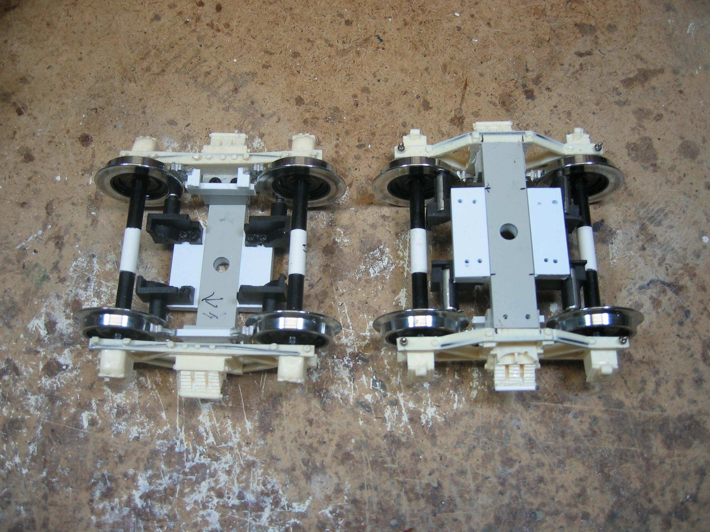
Part I: The Trucks The
first thing that I build is the tender trucks. If you can find some
ready made side frames that will work for your engine, it will save
time. Luckily, Little River 2-4-4-2 #126 used the same tender truck
side frames as those on the D&RGW K-37 for which I had already made
patterns and molds. When I pour casting resin into my molds, I drop
preformed steel rod into the mold. This gives the casting strength,
like steel rods do in concrete. I sand off the back side of the
casting and drill holes into it to accept plastic tube with an
⅛” ID hole. This will be the
journal bearing that the axle
will ride in. Small roller bearings are available, which would work
for high use situations, but styrene bearings have been sufficient for
all my locomotives.
On these particular trucks, I used LGB metal wheel sets, with
3mm axles, which I regauged for Gauge 3 using new 3mm steel rod
from Northwest
Short Line along with a spacer tube to go between the LGB
axle tubes.
   Plastruct
Ľ" X 9/16" rectangular stock is used for bolster material. I super
glue (ACC is my adhesive of choice) the Plastruct bolster to one
side frame and then glue a separate block to the opposite side
frame. Using LGB screws, I then screw the assembly together on one
side to make
a rolling truck. Wheel sets are replaceable by disassembling one
side frame from the bolster. Plastruct
Ľ" X 9/16" rectangular stock is used for bolster material. I super
glue (ACC is my adhesive of choice) the Plastruct bolster to one
side frame and then glue a separate block to the opposite side
frame. Using LGB screws, I then screw the assembly together on one
side to make
a rolling truck. Wheel sets are replaceable by disassembling one
side frame from the bolster.
Since I use track power,
electrical pickup is via bolster mounted wheel wipers; and here, I use LGB
plunger style pickups.
For Gauge 3, I added additional mounting blocks to the bolster and
cut the LGB wiper holders in half. I then insert the brushes into
the holders and screw the holders to the mounting blocks. I wire them after
everything is built.
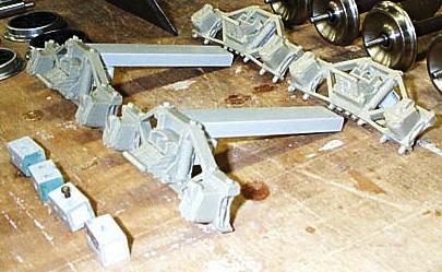
Ozark Miniatures brake shoes were
then mounted to
plastic strip and glued to the bolster.
Trackside Details
makes chain mounting eyelets that I mount to the top corners of the side
frames. I drill a 17/64” hole in the center of the bolster that a
Ľ” tube can go through. The trucks are done for now.
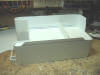
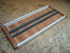 Part
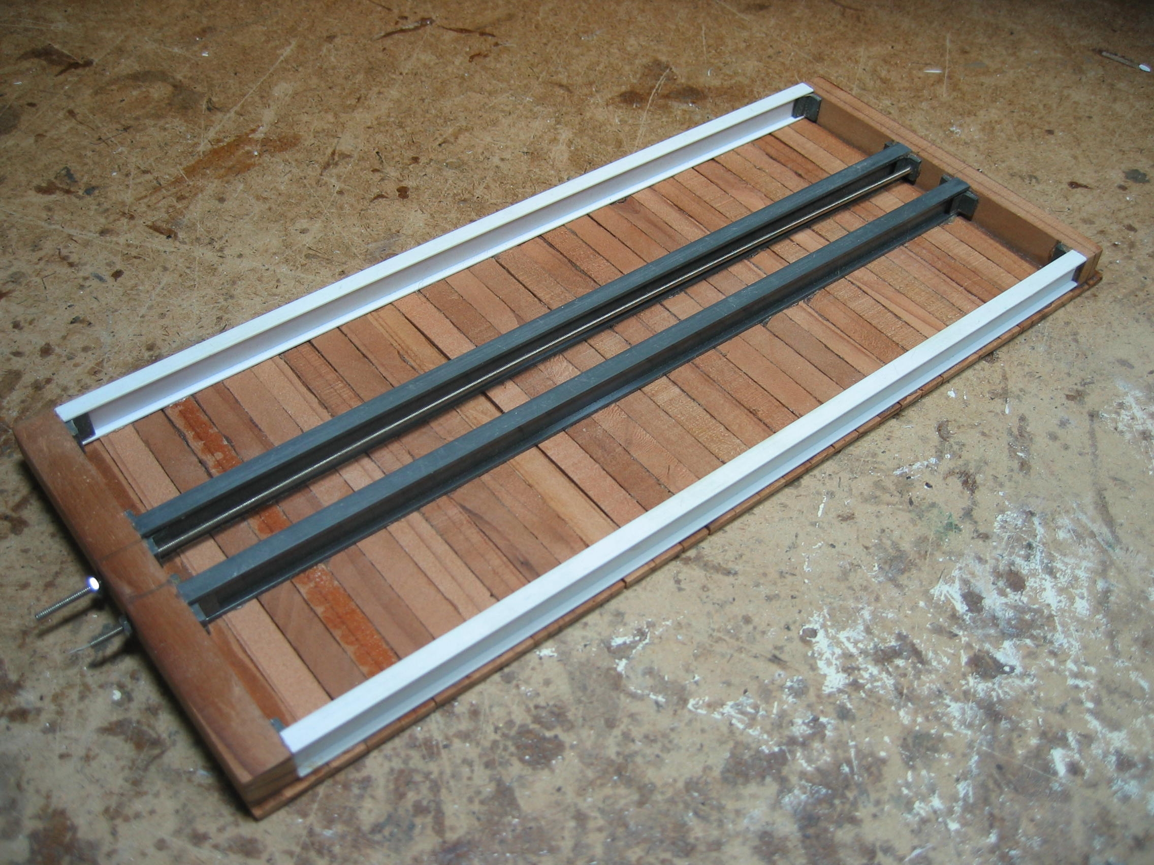
II: The Tender Deck I usually build the tender deck using
plastic for the structure and metal castings for the details.
Since Dave Queener started this project, I decided to use the basic deck
that he had made. Dave made the frame rails out of styrene channels with wood
end beams and a wooden deck. Dave then added two 2-56 threaded rods
running the length of
the deck to make sure the end beams could not be pulled apart. The real wood looks good on this tender.
I usually make my end beams out of large plastic strips and drag a coarse
Zona saw across them to give the look of wood.
Likewise, the deck is usually a sandwich of 0.040"
Evergreen scribed siding (with
Ľ" spacing) with
another sheet on top aligned to the scribes on the bottom. I drag
the Zona saw across both top and bottom sheets to make them look like wood. Part
II: The Tender Deck I usually build the tender deck using
plastic for the structure and metal castings for the details.
Since Dave Queener started this project, I decided to use the basic deck
that he had made. Dave made the frame rails out of styrene channels with wood
end beams and a wooden deck. Dave then added two 2-56 threaded rods
running the length of
the deck to make sure the end beams could not be pulled apart. The real wood looks good on this tender.
I usually make my end beams out of large plastic strips and drag a coarse
Zona saw across them to give the look of wood.
Likewise, the deck is usually a sandwich of 0.040"
Evergreen scribed siding (with
Ľ" spacing) with
another sheet on top aligned to the scribes on the bottom. I drag
the Zona saw across both top and bottom sheets to make them look like wood.
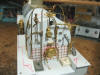
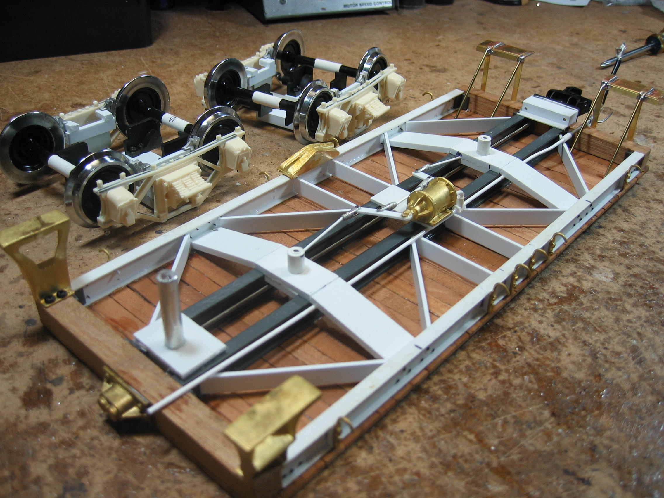
 With the basic deck done, it is time to make
some decisions. Most plans and O scale models have very little or no
under deck details. The O scale model I examined for this engine was no exception.
In cases like this, the best thing to
do is to take some pictures of a prototype tender about the same size or find
another O scale model that has underbody details. I looked at a
brass D&RGW K37 in On3
for some clues. What you see on the
completed deck is what I came up with. The underframe braces, for
instance, are cut from
plastic strip and glued on. The next step is to measure the height of the
top of the deck to the top of the rail on the plan. I slide the
completed trucks under the new deck and start filling the space
between the top of the truck bolsters and the frame rails of the
deck with plastic strip, until I get the deck height correct. Once
you find the correct thickness, cut and glue the strips to the frame
rails the right length from the ends of the deck, according to the
plan. With the basic deck done, it is time to make
some decisions. Most plans and O scale models have very little or no
under deck details. The O scale model I examined for this engine was no exception.
In cases like this, the best thing to
do is to take some pictures of a prototype tender about the same size or find
another O scale model that has underbody details. I looked at a
brass D&RGW K37 in On3
for some clues. What you see on the
completed deck is what I came up with. The underframe braces, for
instance, are cut from
plastic strip and glued on. The next step is to measure the height of the
top of the deck to the top of the rail on the plan. I slide the
completed trucks under the new deck and start filling the space
between the top of the truck bolsters and the frame rails of the
deck with plastic strip, until I get the deck height correct. Once
you find the correct thickness, cut and glue the strips to the frame
rails the right length from the ends of the deck, according to the
plan.
 I use a
Ľ" tube or rod to make the pivot
point for the trucks. Drill through the center point of the plastic
body bolster and through the deck, if it is plastic, to make sure the pivot
rod is secured when glued in place. Glue the tube or rod in place
and slip the truck over it. Mark the rod or tube about 1/16” above
the truck bolster and take the truck off. Cut it at the mark and
drill a small pilot hole for a screw and washer to hold the truck
on. In addition, a metal Ľ” rod is used for the draw bar pin on
this model. To secure it, I use plastic block and strips glued to the inside frame
rails, dilled to accept the rod. I use a
Ľ" tube or rod to make the pivot
point for the trucks. Drill through the center point of the plastic
body bolster and through the deck, if it is plastic, to make sure the pivot
rod is secured when glued in place. Glue the tube or rod in place
and slip the truck over it. Mark the rod or tube about 1/16” above
the truck bolster and take the truck off. Cut it at the mark and
drill a small pilot hole for a screw and washer to hold the truck
on. In addition, a metal Ľ” rod is used for the draw bar pin on
this model. To secure it, I use plastic block and strips glued to the inside frame
rails, dilled to accept the rod.
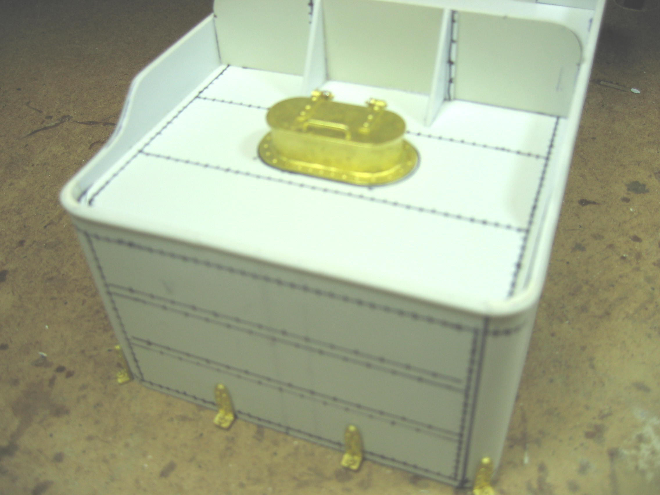
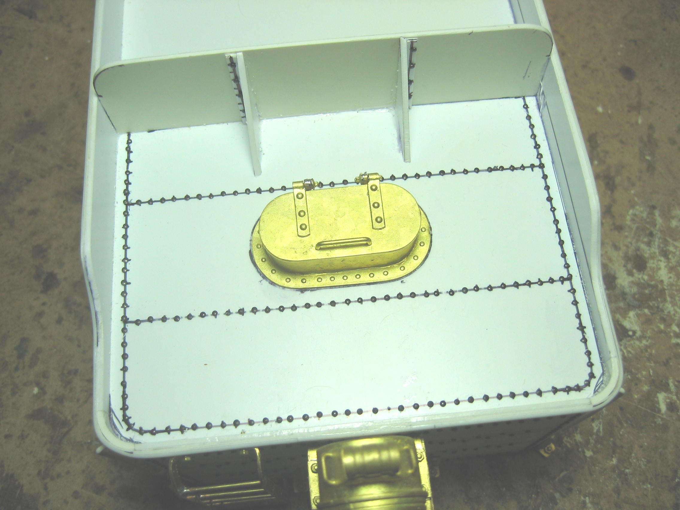
  Once
the trucks are on, add all the piping and detail parts to the deck,
according to the plan. With the bottom done, mark and drill for the
rivet detail on the side rails. I use a #74 drill bit and
Peco track fixing pins cut to about
⅛” long,
for rivets. These are used on all other areas of the engine that
call for rivet detail. With the rivets on, add all remaining details
such as steps and buffers. I mounted a
Kadee
"G" scale end beam coupler pocket
and knuckle to this model, because it will be a logging engine. On most
on my narrow gauge engines, I truck mount the coupler, to better
couple and uncouple on tight curves. Body-mounted or truck-mounted:
It's your choice. Finally, I added brass steps and cut levers to the
rear of the tender deck. I drill the deck for both speaker holes and
wiring once the tender is done. With the deck finished and
rolling, it’s time to start on the tender tank. Once
the trucks are on, add all the piping and detail parts to the deck,
according to the plan. With the bottom done, mark and drill for the
rivet detail on the side rails. I use a #74 drill bit and
Peco track fixing pins cut to about
⅛” long,
for rivets. These are used on all other areas of the engine that
call for rivet detail. With the rivets on, add all remaining details
such as steps and buffers. I mounted a
Kadee
"G" scale end beam coupler pocket
and knuckle to this model, because it will be a logging engine. On most
on my narrow gauge engines, I truck mount the coupler, to better
couple and uncouple on tight curves. Body-mounted or truck-mounted:
It's your choice. Finally, I added brass steps and cut levers to the
rear of the tender deck. I drill the deck for both speaker holes and
wiring once the tender is done. With the deck finished and
rolling, it’s time to start on the tender tank.
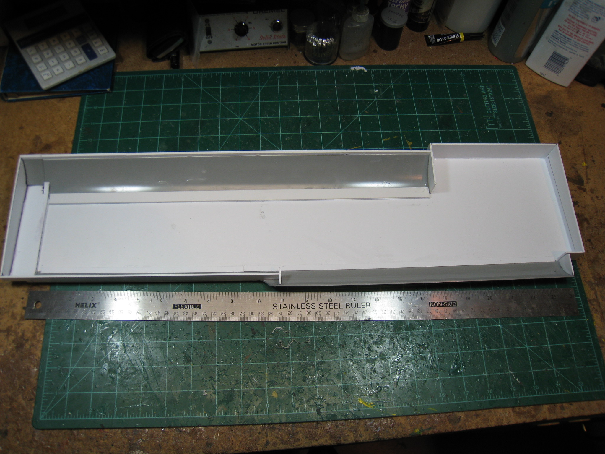
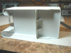
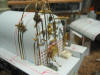
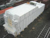
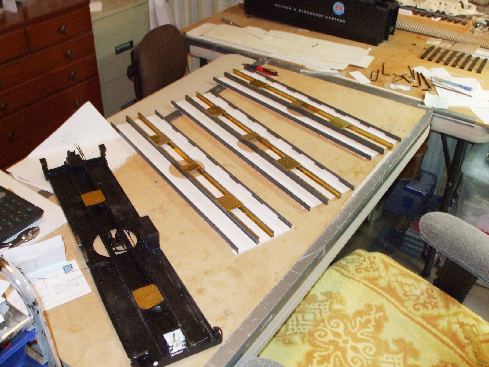
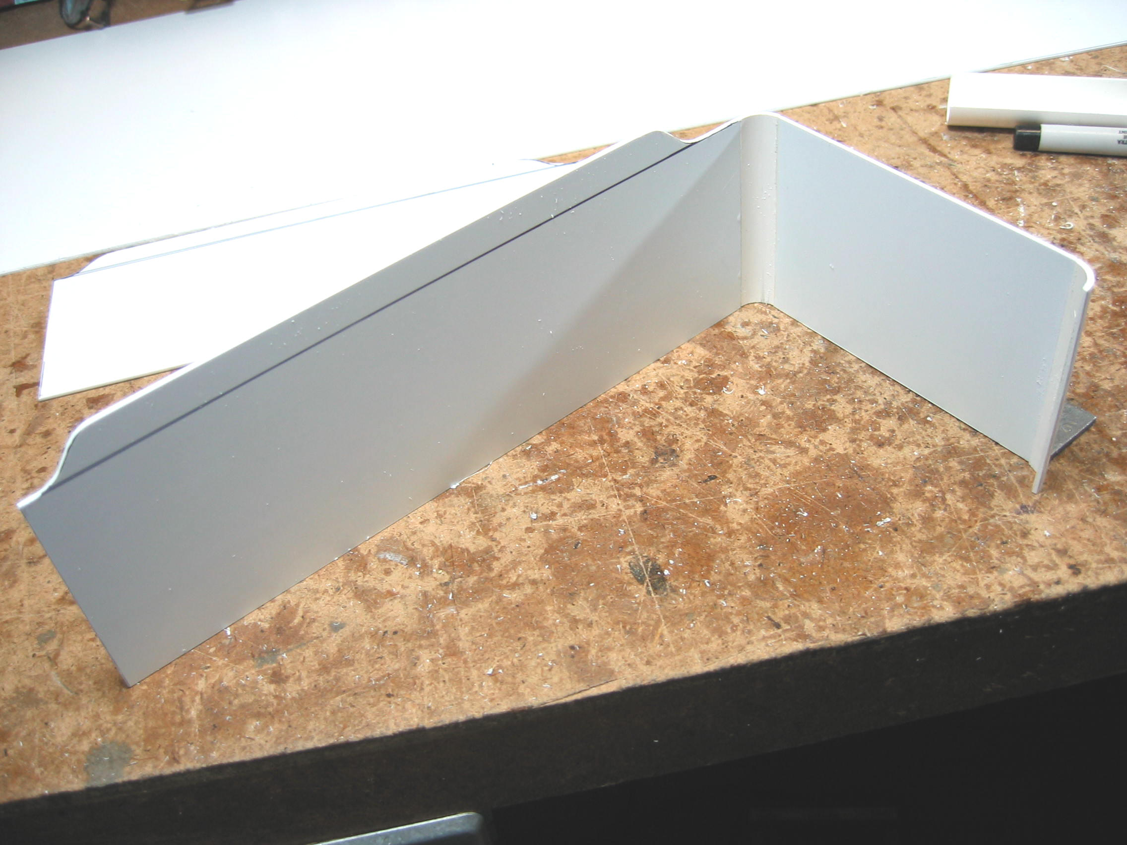
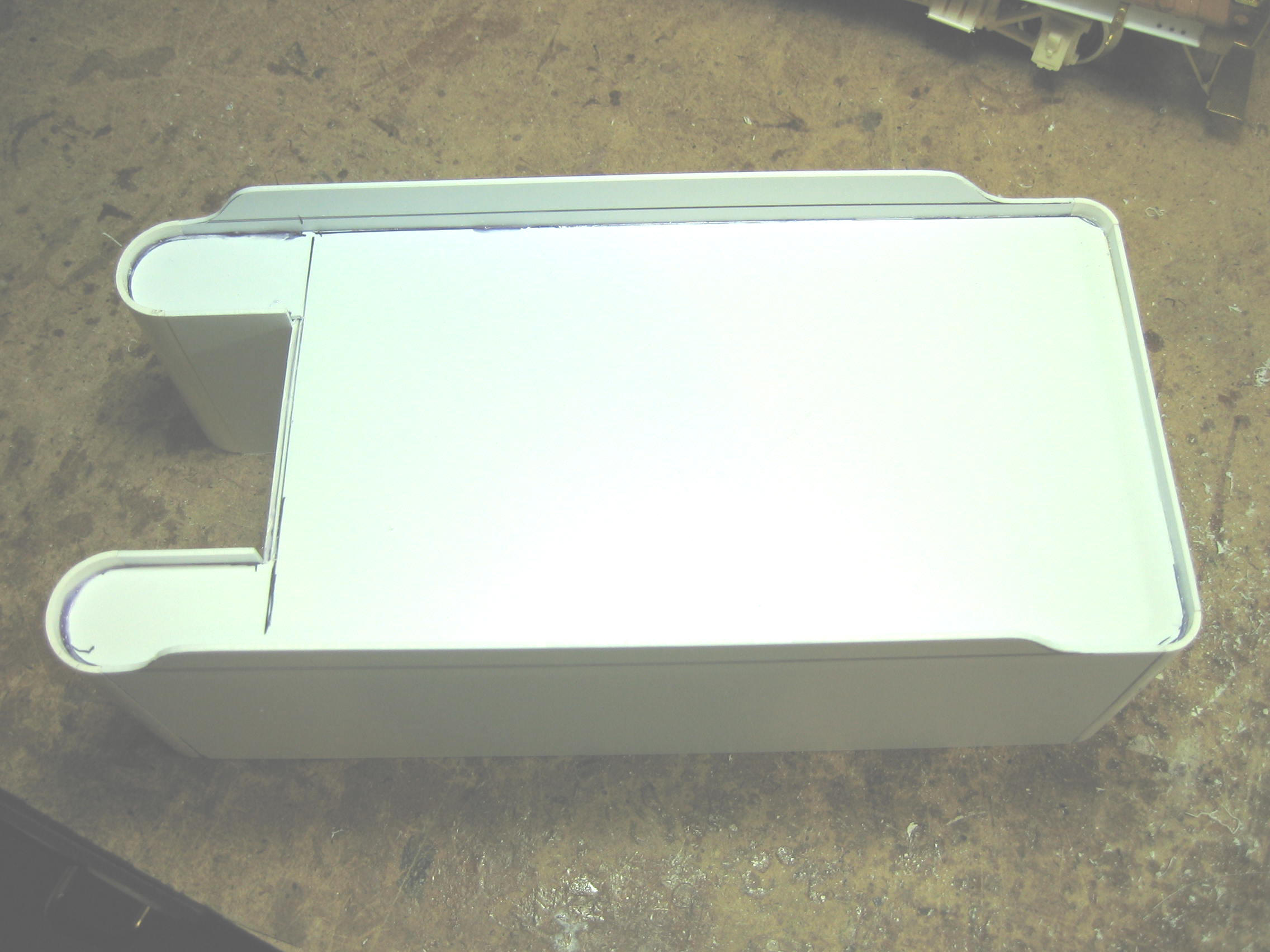
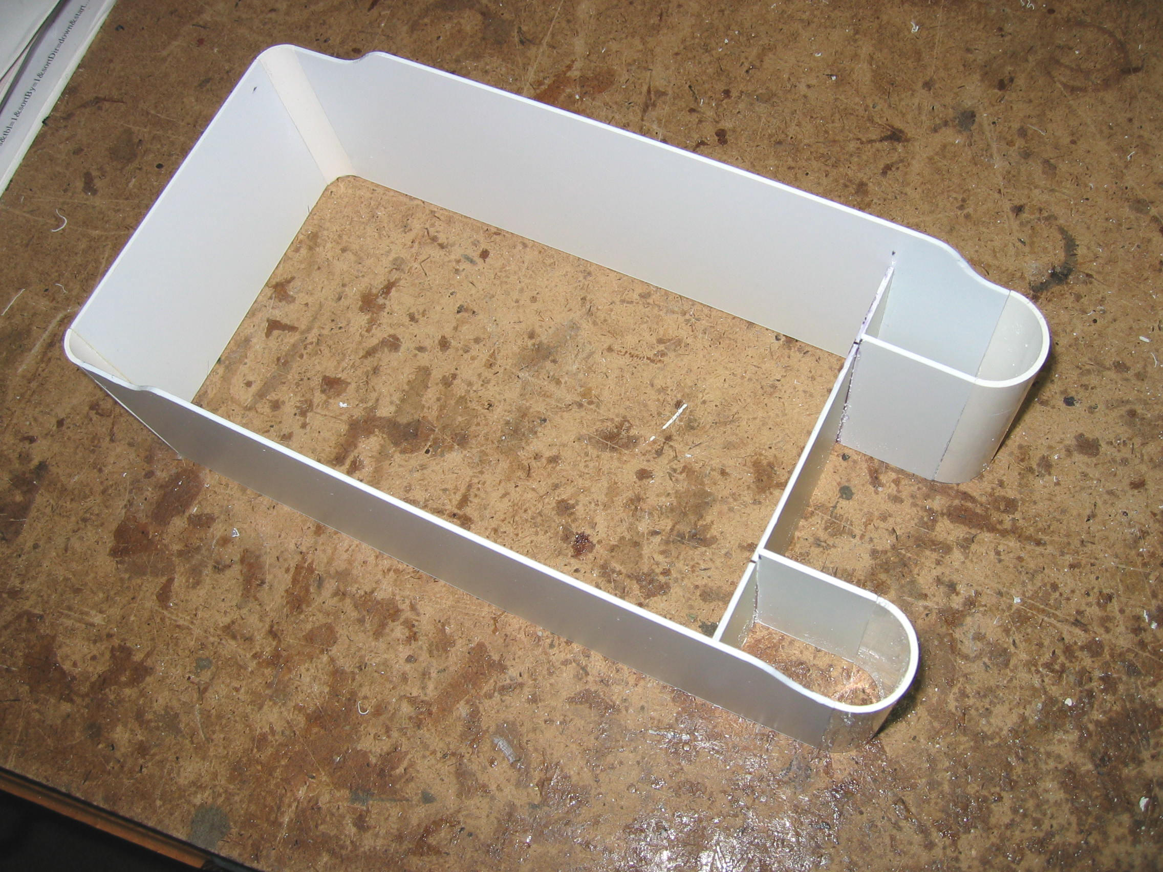
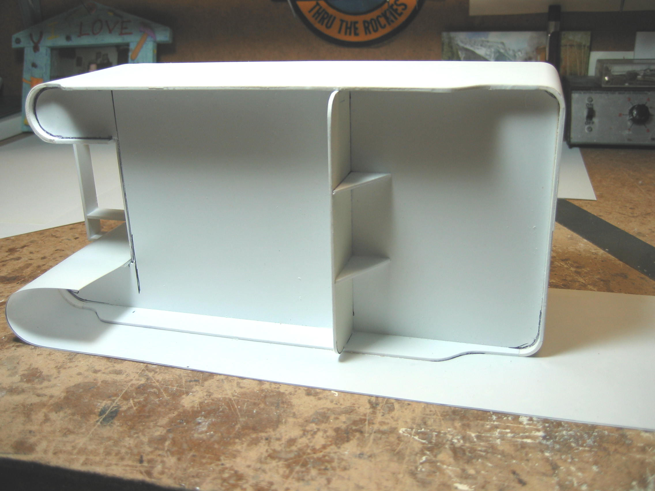
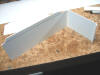   Part III: The
Tender Tank Now that the deck is done, the tank can
begin. I design my tender tanks to be light weight, but strong. The
basic design is a 0.060" sheet plastic box, with a 0.010" plastic
wrapper. The reason for using 0.060" plastic is that Plastruct tube
has the same wall thickness. The structure of the tender tank is
made using this 0.060" styrene mated to quartered pieces of
Plastruct tube on the "corners" of the tank. Start with your scale
drawing. If you have a top
view of the tender, match the curved sides of the tank with the
correct diameter of Plastruct tube. The next task is to cut the tube
to length. Mark a straight line along the side of the tube next. To
do this, I lay it in a mini miter box and draw a line in ink with a
Sharpie pen using the top edge of the box as my guide. I measure the circumference of the tube next
and divide it in half or quarters, depending on the need. A fine
tooth razor or Zona saw is then used to cut the lines drawn. Hold the
tube in a vice while you cut it. Clean the edges, and it’s ready to
glue to the sides. Cut out the tank side and end profiles from the
0.060" plastic sheet. Glue the corners with a butt joint, using
super glue or ACC. Use a small square to make sure the box is
square. Part III: The
Tender Tank Now that the deck is done, the tank can
begin. I design my tender tanks to be light weight, but strong. The
basic design is a 0.060" sheet plastic box, with a 0.010" plastic
wrapper. The reason for using 0.060" plastic is that Plastruct tube
has the same wall thickness. The structure of the tender tank is
made using this 0.060" styrene mated to quartered pieces of
Plastruct tube on the "corners" of the tank. Start with your scale
drawing. If you have a top
view of the tender, match the curved sides of the tank with the
correct diameter of Plastruct tube. The next task is to cut the tube
to length. Mark a straight line along the side of the tube next. To
do this, I lay it in a mini miter box and draw a line in ink with a
Sharpie pen using the top edge of the box as my guide. I measure the circumference of the tube next
and divide it in half or quarters, depending on the need. A fine
tooth razor or Zona saw is then used to cut the lines drawn. Hold the
tube in a vice while you cut it. Clean the edges, and it’s ready to
glue to the sides. Cut out the tank side and end profiles from the
0.060" plastic sheet. Glue the corners with a butt joint, using
super glue or ACC. Use a small square to make sure the box is
square.
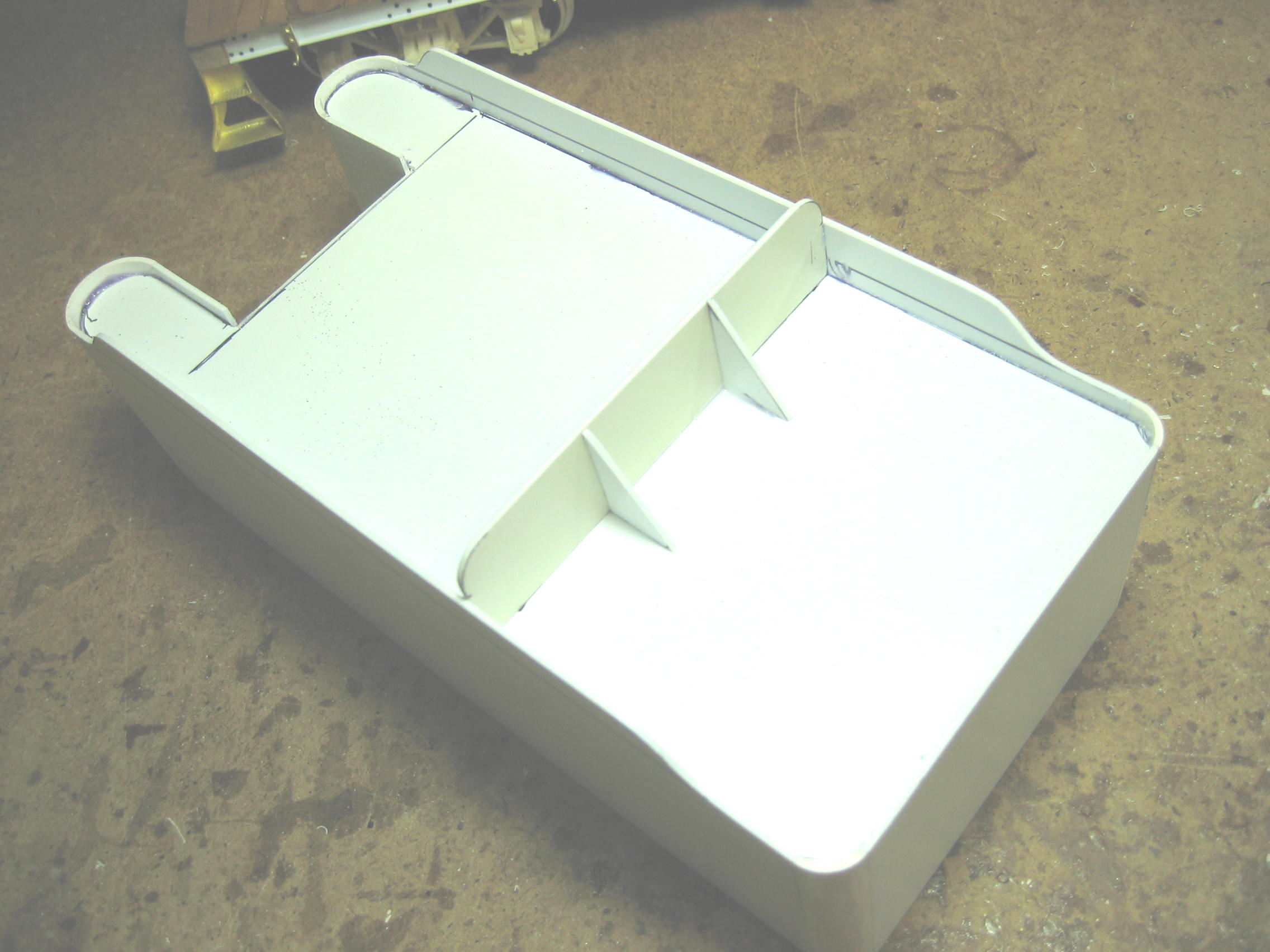
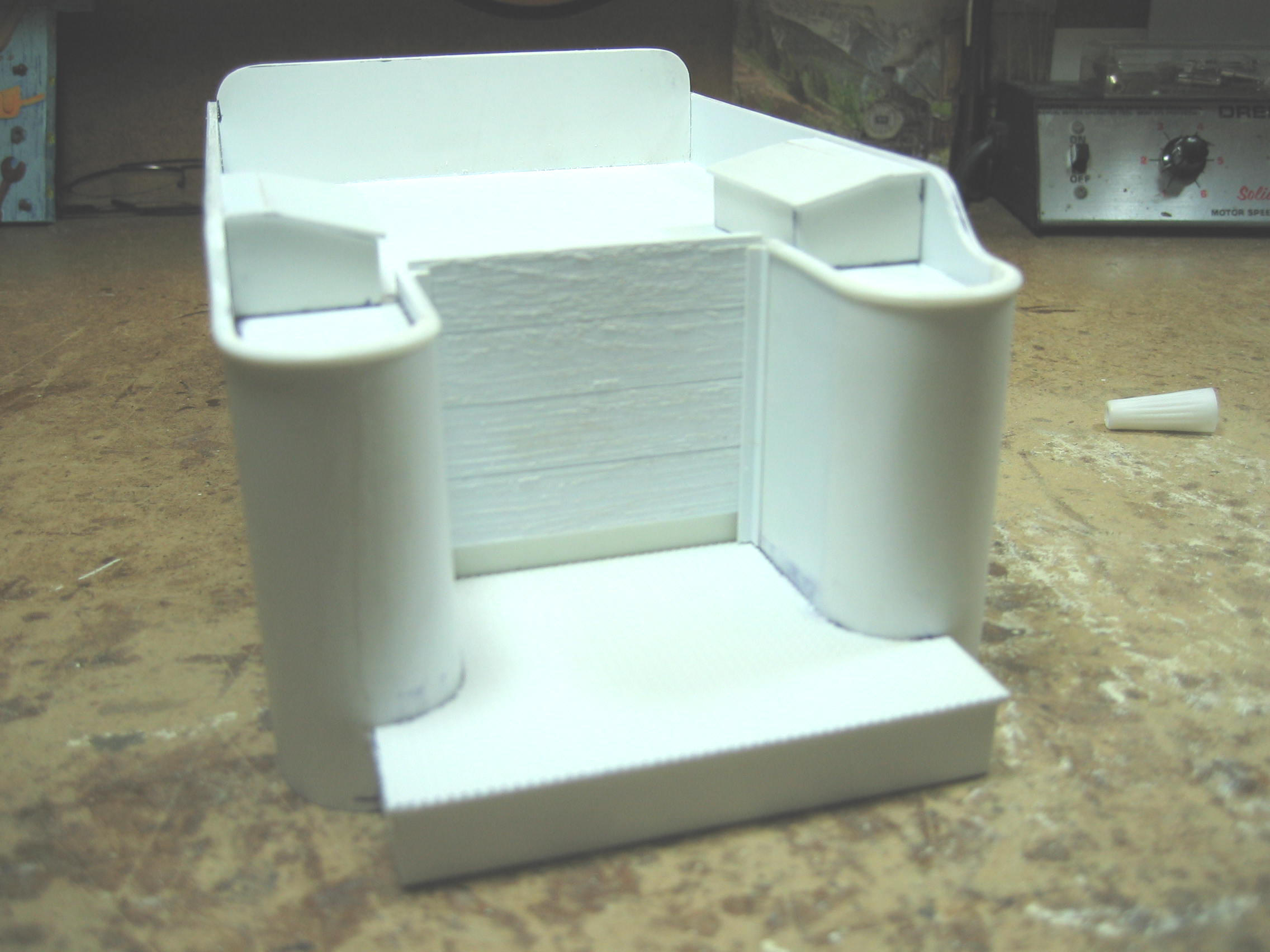
    I use ACC kicker to speed the setting of the
joints. Be careful with the tank, as the super glued joint is all that is
holding it together. Using more sheet plastic, I make a piece to go
across the inside width of the tank, behind the coal door area. Glue
it to the inside of both sides, and the front water legs of the
tank. This one piece will stiffen up the tank to handle it. I prefer
not to make the deep coal area of the tank. Instead, I put a full
sheet of plastic across the area, all the way to the back end of the
tank. I file the corners to fit the rear curves and glue it in place
at the correct height from the top edge of the tank walls. ACC it
from the bottom so the glue joint will not show. With this joint
made, the tank will be much stiffer and you will have the basic tank
done. ⅜" angle Plastruct pieces are
glued to the inside bottom edge of the tank. This makes the bottom
of the sides rigid. I then glue about an inch wide strip, the
inside width of the tank, up on top of the angles, at each end.
These pieces tie the side angles with the end angle and make the
tank even stronger. With this step done, it is time to add the coal
doors and additional structure around the area. I use ACC kicker to speed the setting of the
joints. Be careful with the tank, as the super glued joint is all that is
holding it together. Using more sheet plastic, I make a piece to go
across the inside width of the tank, behind the coal door area. Glue
it to the inside of both sides, and the front water legs of the
tank. This one piece will stiffen up the tank to handle it. I prefer
not to make the deep coal area of the tank. Instead, I put a full
sheet of plastic across the area, all the way to the back end of the
tank. I file the corners to fit the rear curves and glue it in place
at the correct height from the top edge of the tank walls. ACC it
from the bottom so the glue joint will not show. With this joint
made, the tank will be much stiffer and you will have the basic tank
done. ⅜" angle Plastruct pieces are
glued to the inside bottom edge of the tank. This makes the bottom
of the sides rigid. I then glue about an inch wide strip, the
inside width of the tank, up on top of the angles, at each end.
These pieces tie the side angles with the end angle and make the
tank even stronger. With this step done, it is time to add the coal
doors and additional structure around the area.
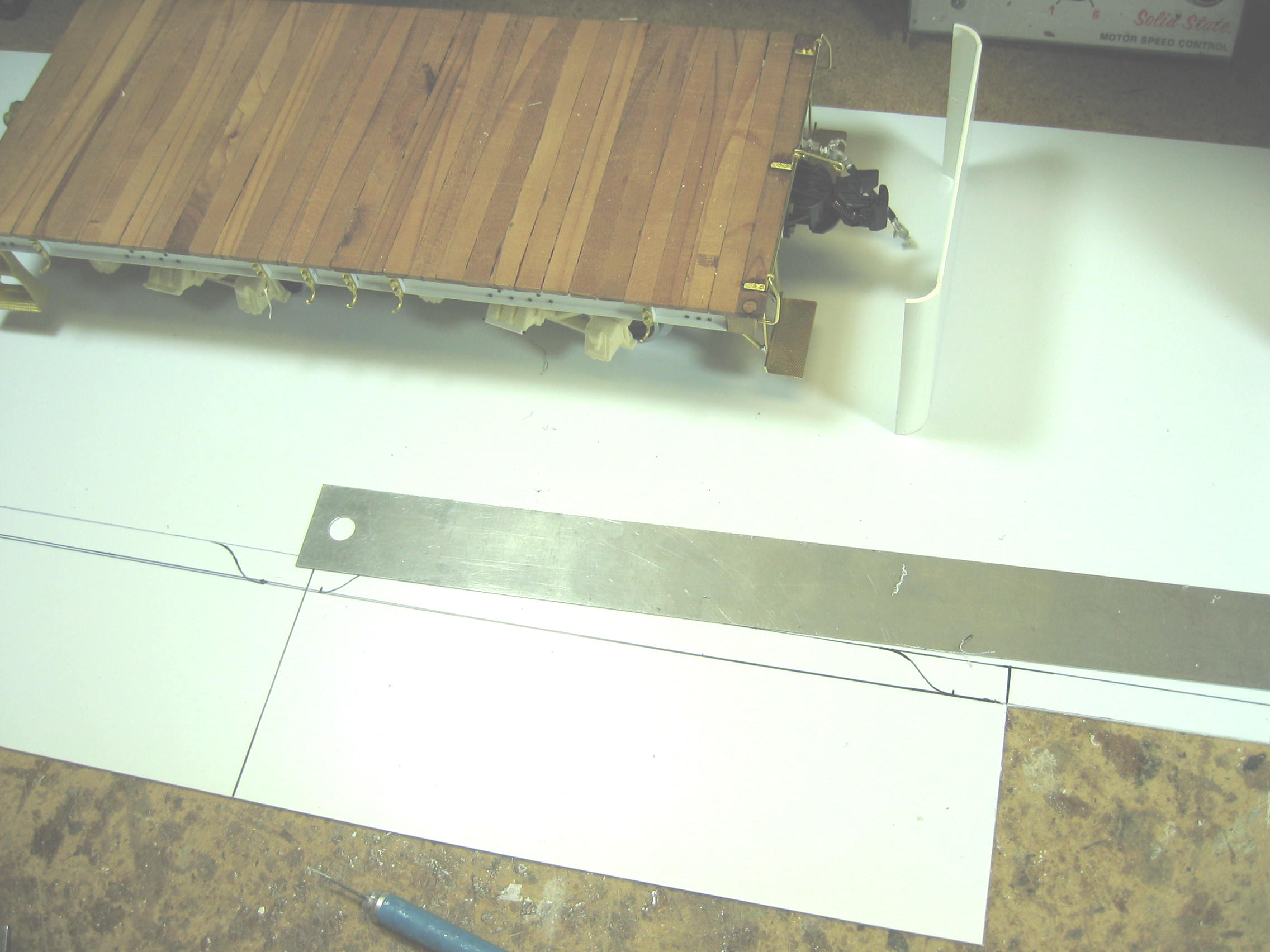
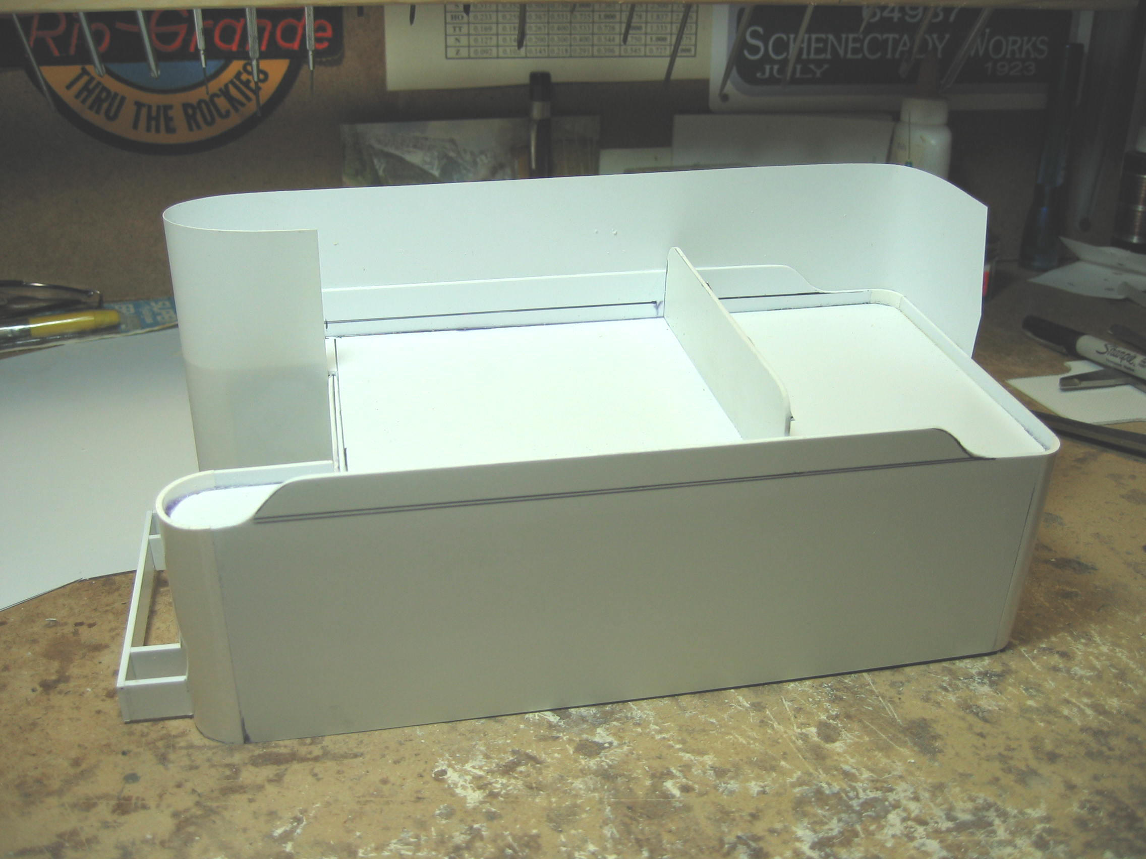
      You now have the shape of the tender, but it
has joints showing. I file the joints down to make sure they are
smooth with either sandpaper or a file. Now is the time to make sure that
the tank is correct to the plan and that no revisions need to be made. I
test fit it to the deck and check to make sure it sits squarely in
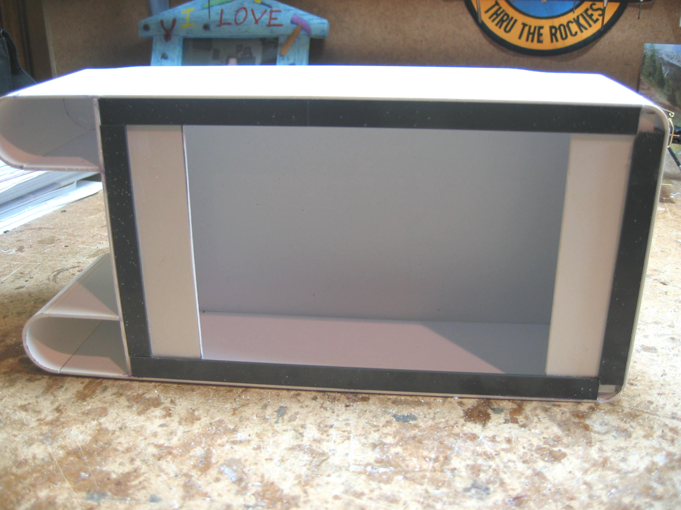
place. The next step is to apply the 0.010 " plastic wrapper. I
cut out a piece of sheet plastic that is about an inch wider than
the top and bottom of the sides of the tank. The length of the
wrapper should be from the coal doors, around the sides, to the
middle of the back of the tank. Starting at the coal door area, glue the edge
of the 0.010" sheet next to the door area. Make sure that when it
is glued, the rest of the sheet will cover the side and end. Now put
ACC on the entire area of the water leg, around the front to the
first joint with the side. Lay the 0.010" plastic sheet down and
pull it around the front of the water leg to the side joint. Make
sure that it is flat with no buckles in the plastic sheet. Hold the
sheet until the glue sets. Be careful not to kink the thin 0.010"
sheet, as it could break. I had to fix a crack on one of my water
legs, because the sheet was creased before I used it." You now have the shape of the tender, but it
has joints showing. I file the joints down to make sure they are
smooth with either sandpaper or a file. Now is the time to make sure that
the tank is correct to the plan and that no revisions need to be made. I
test fit it to the deck and check to make sure it sits squarely in
place. The next step is to apply the 0.010 " plastic wrapper. I
cut out a piece of sheet plastic that is about an inch wider than
the top and bottom of the sides of the tank. The length of the
wrapper should be from the coal doors, around the sides, to the
middle of the back of the tank. Starting at the coal door area, glue the edge
of the 0.010" sheet next to the door area. Make sure that when it
is glued, the rest of the sheet will cover the side and end. Now put
ACC on the entire area of the water leg, around the front to the
first joint with the side. Lay the 0.010" plastic sheet down and
pull it around the front of the water leg to the side joint. Make
sure that it is flat with no buckles in the plastic sheet. Hold the
sheet until the glue sets. Be careful not to kink the thin 0.010"
sheet, as it could break. I had to fix a crack on one of my water
legs, because the sheet was creased before I used it."
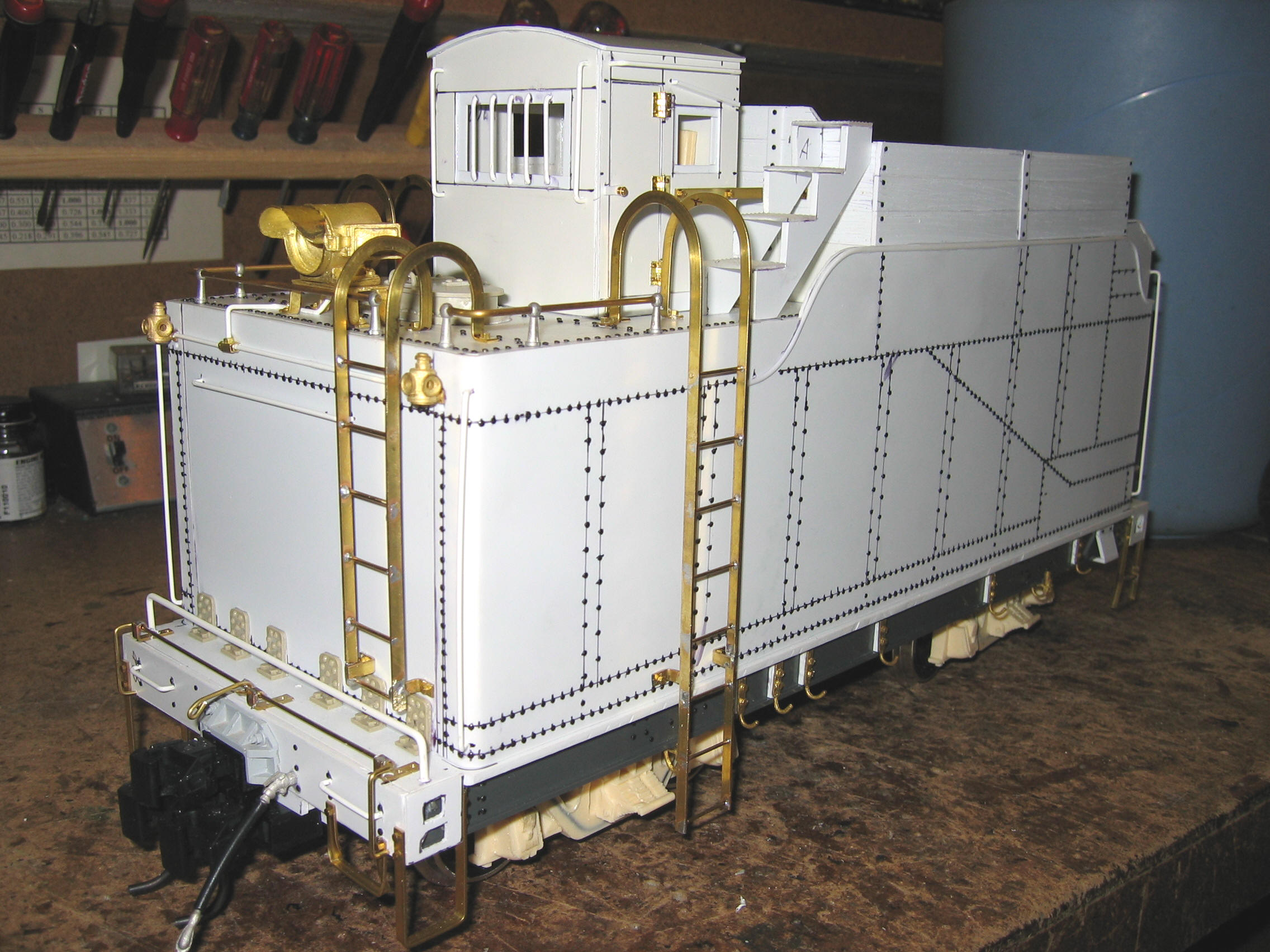
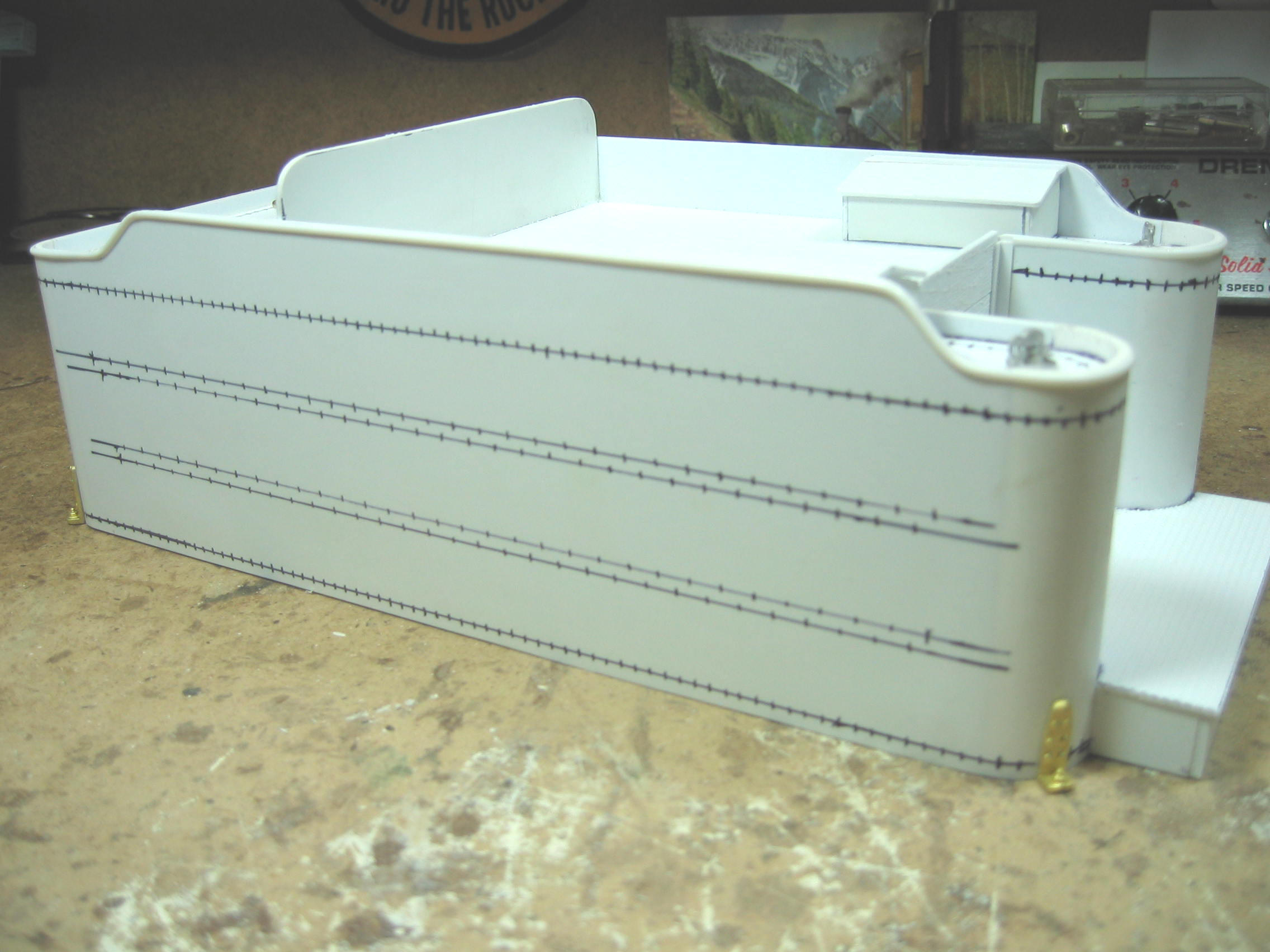
Barry's
narrative ends at this point, but the remaining work chiefly
concerns adding rivet detail to the tender body, beading to the
edges of the tank's sides, and various detail parts. The end result
speaks for itself.

_small.JPG)
 |
|
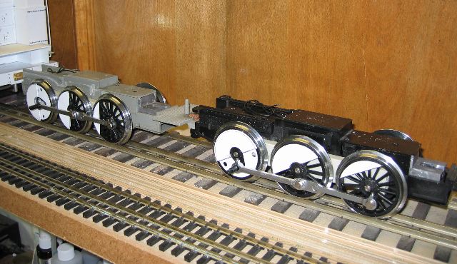
The Chassis, Boiler &
Cab The
remainder of Barry's 2-4-4-2 was built in typical Bogsian fashion:
LGB motor blocks sandwiched by new styrene frames, side and main
rods adapted from other LGB locomotives (in this case from both the
Stainz 0-4-0 and the Mikado). The boiler itself is Plastruct tube.
The cast urethane domes are Barry's own creations. The usual
complement of
Ozark Miniatures,
Trackside Details,
and
Precision Scale detail parts round out this outstanding
model. Now where can I get mine--in 1:20.3 Standard Gauge?
_small.JPG)
_small.JPG)
|
|
The Completed Locomotive
_small.JPG)
_small.JPG)
 _small.JPG)
_small.JPG)
_small.JPG)
|
|
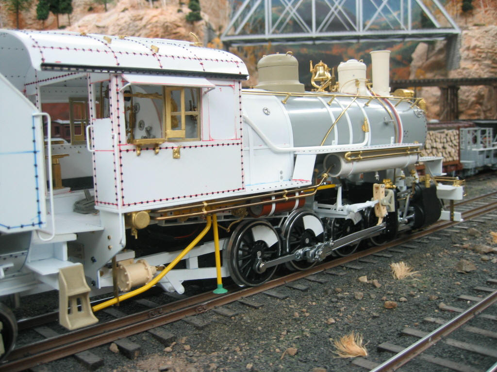
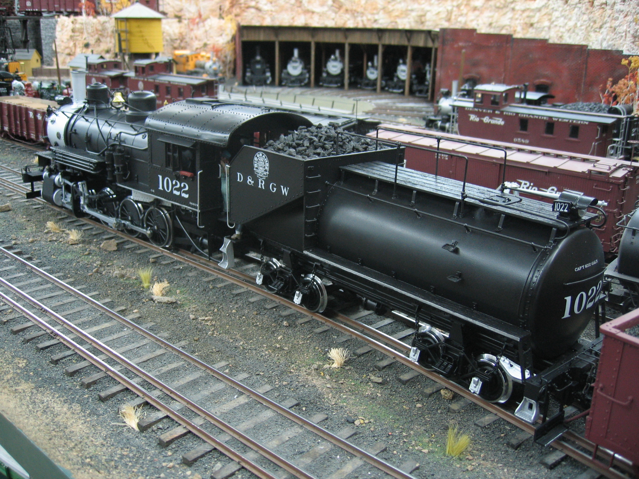
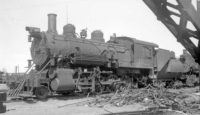
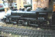
.jpg) D&RGW
C-41 2-8-0 D&RGW
C-41 2-8-0
(2007)
Built in 1902 by Baldwin, the D&RGW C-41 was a heavy consolidation
for its time, exerting 40,893 lbs. of tractive effort from its 55"
drivers. Overall dimensions, with tender, were 63'-3" long, 10'-2"
wide and 15'-1" tall (track to stack). Each tender carried 9 tons of
coal and 6000 gallons of water. Stephenson valve gear and slide
valve cylinders were original equipment on these locomotives;
however with the advent of superheaters, many of the C-41s were
rebuilt with piston valves and at least two locomotives (#1022 and
#1024) were refitted with Walschaert's valve gear. Over time some of
these engines even acquired Vanderbilt tenders, much like their
larger 1916 vintage 2-10-2 cousins on the D&RGW.
The C-41's single
claim to fame lies in the 1930 conversion of ten of this class to
D&RGW K-37 narrow gauge 2-8-2s, each "new" K-37 receiving the
rectangular tender, archbar tender trucks, boiler, domes & cab of
its C-41 predecessor. New running gear--outside frames, 44" drivers,
piston valve cylinders, outside bearing lead & trailing trucks, rods
and such--were provided by Baldwin. Tender trucks were simply
regauged, retaining their standard gauge bolsters while pressing
new, smaller
wheels several inches closer together on otherwise standard
gauge axles. Most likely new
smoke boxes, petticoat pipes and stacks were applied, as was a new cab
apparently patterned after those on the K-36, and hence, a bit
shorter and more narrow than the C-41 original. In any case, none of the other twenty unconverted C-41s
escaped the scrapper's torch; and to the best that Barry and I have
been able to determine, no D&RGW drawings of the C-41 have survived
either. If anyone is aware of either blueprints of these locomotives or
pictures of the 1930 conversion, please drop
me a note. |
|
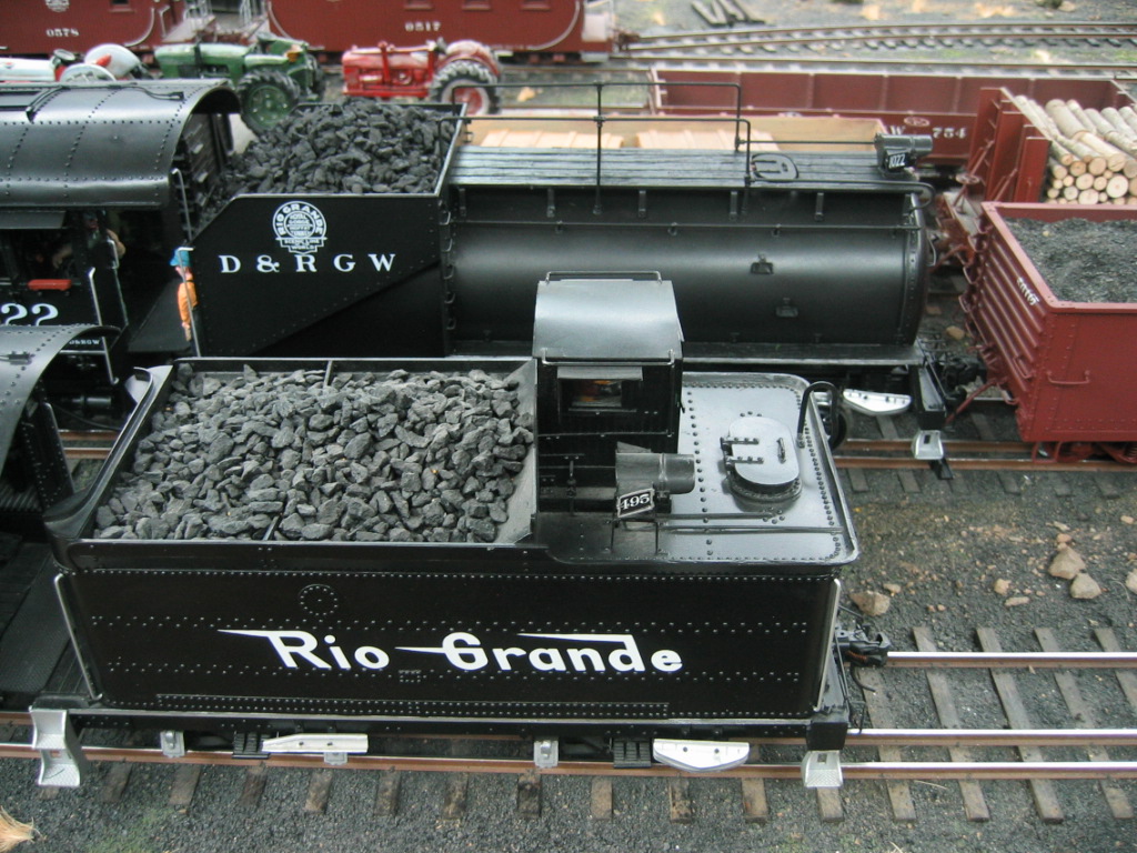
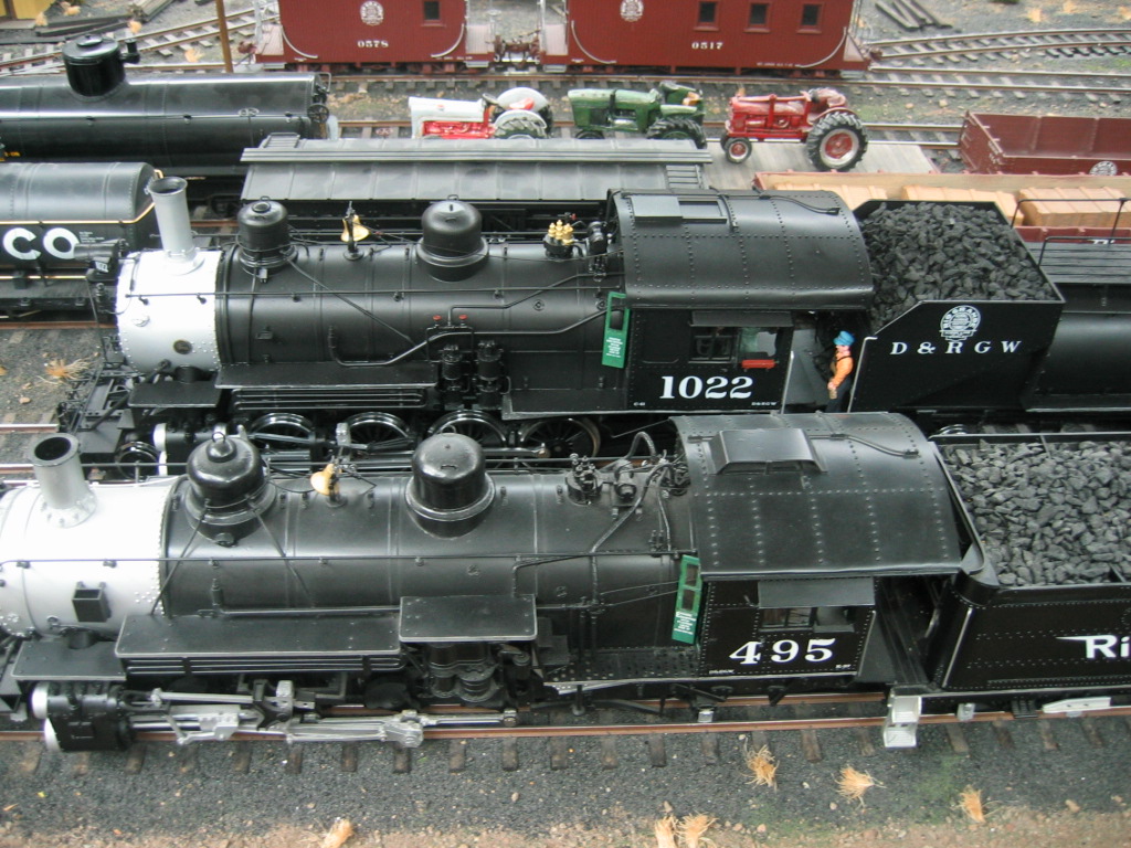
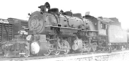
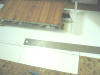
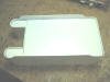
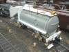
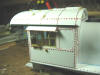
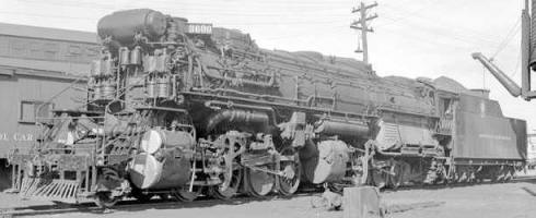
The Tender
Having built many a boxy conventional
tender in the past, Barry chose to do something a bit different for
the C-41, choosing locomotive #1022
(pictured above) as his prototype.
This is the first Vanderbilt tender he has done; but much like the
prototype, it rides upon the very same archbar trucks as used on the
K-37, Barry having built several of these over the past number of
years. Aside from styrene, Trackside Details parts, and the usual
combination of regauged LGB wheelsets, the tender is essentially a
3" OD length of ABS tube from Plastruct, complete with end cap. Now
that Barry has shown the way, let's see somebody build one of these
in F scale!

 |
|
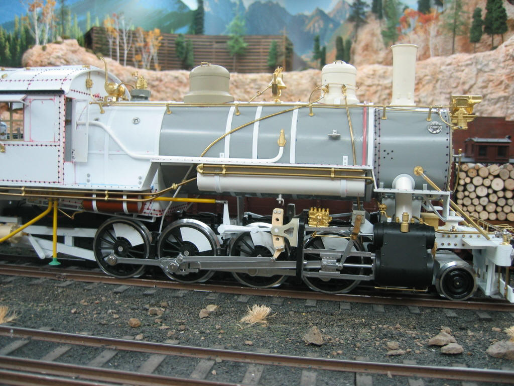
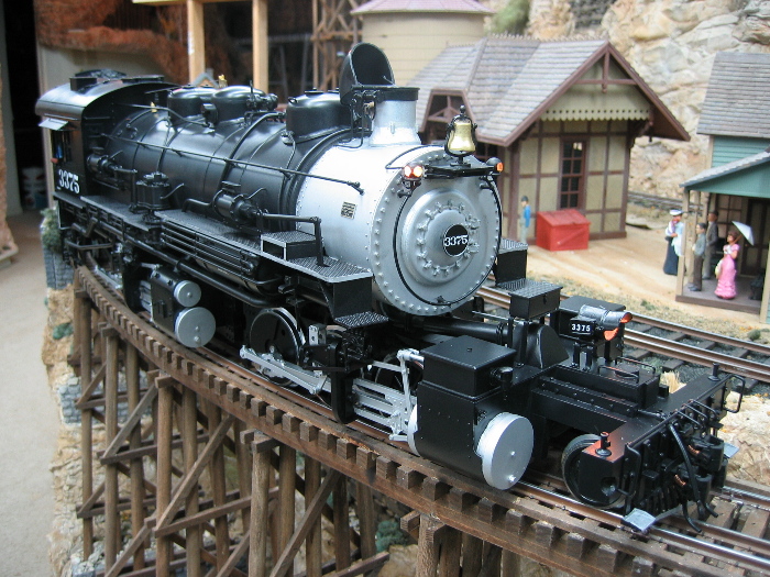
The Chassis, Boiler &
Cab
Barry's main
interest in building the C-41 is to show what the K-37 predecessor
looked like--a first in any scale to the best of our knowledge. The
irony is that the construction of the model was the reverse process
regarding the construction of the prototype: Barry began with narrow
gauge components and regauged them to standard gauge! For instance,
aside from the regauged K-37 tender trucks, the running gear for
Barry's 2-8-0 is a Gauge 1, LGB Mikado drive unit. The LGB Mikado
drivers were retained, with changes to the counterweights, but
regauged using new 6mm stainless steel axles. A regauged LGB Gauge 1
wheelset was also used for the lead truck. Walschaerts valve gear
from the LGB Mikado was retained, although several pieces were
replaced with Barry's own castings to more accurately represent
those of the C-41. The boiler is, once again, Plastruct; the domes
and stack are urethane castings from Barry's considerable store of
patterns. The engine has been equipped with a Digitrax DCC decoder
and Phoenix 2K2 sound. It
is capable of negotiating 5' radius curves, the minimum on the Gauge
3 portion of Barry's layout,
and
with its Vanderbilt
tender, measures 33.8" long.

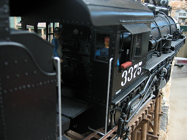
Barry writes in
one of his mid-construction updates: "This week's work on the engine
amounts to cab and backhead details. The cab is so time consuming
because of all the rivets on it. There are more rivets on the
engine, than on the tender! I used dimensions off the D&RGW C-48
2-8-0 for the cab's size, as it is so far off from the K-37. The
back head is just a guess, and a poor one at that, so don't look
real close. I am hoping to come up with an article on the C-41 and
K-37, comparing them side by side, to see how different they really
are. I never understood why the model brass importers did not build
a C-41 and K-37 at the same time and release them together; but now
that I have built them, I have found so much that is dissimilar, it
would not have made sense."


 |
|
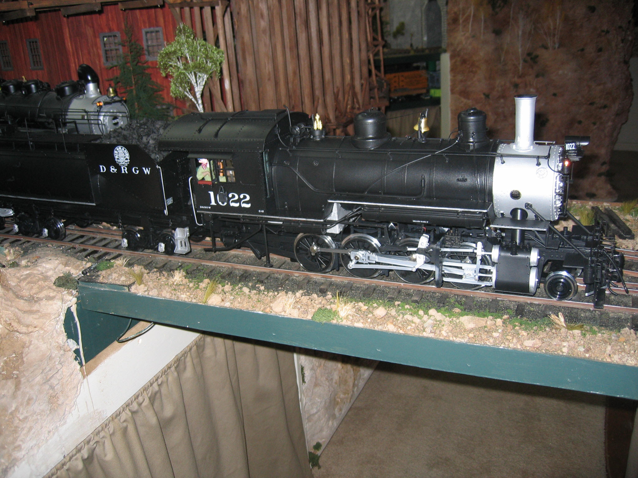
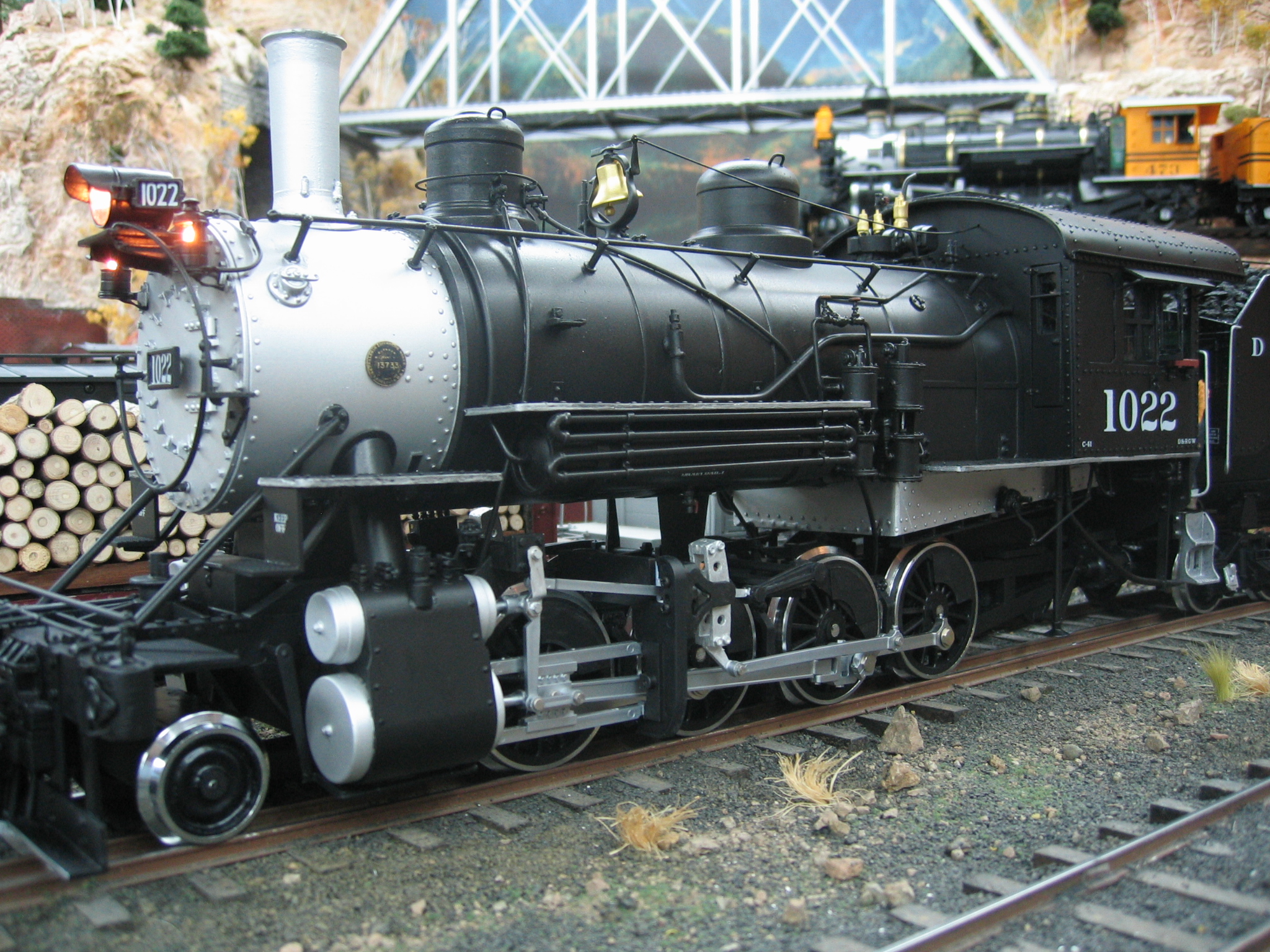
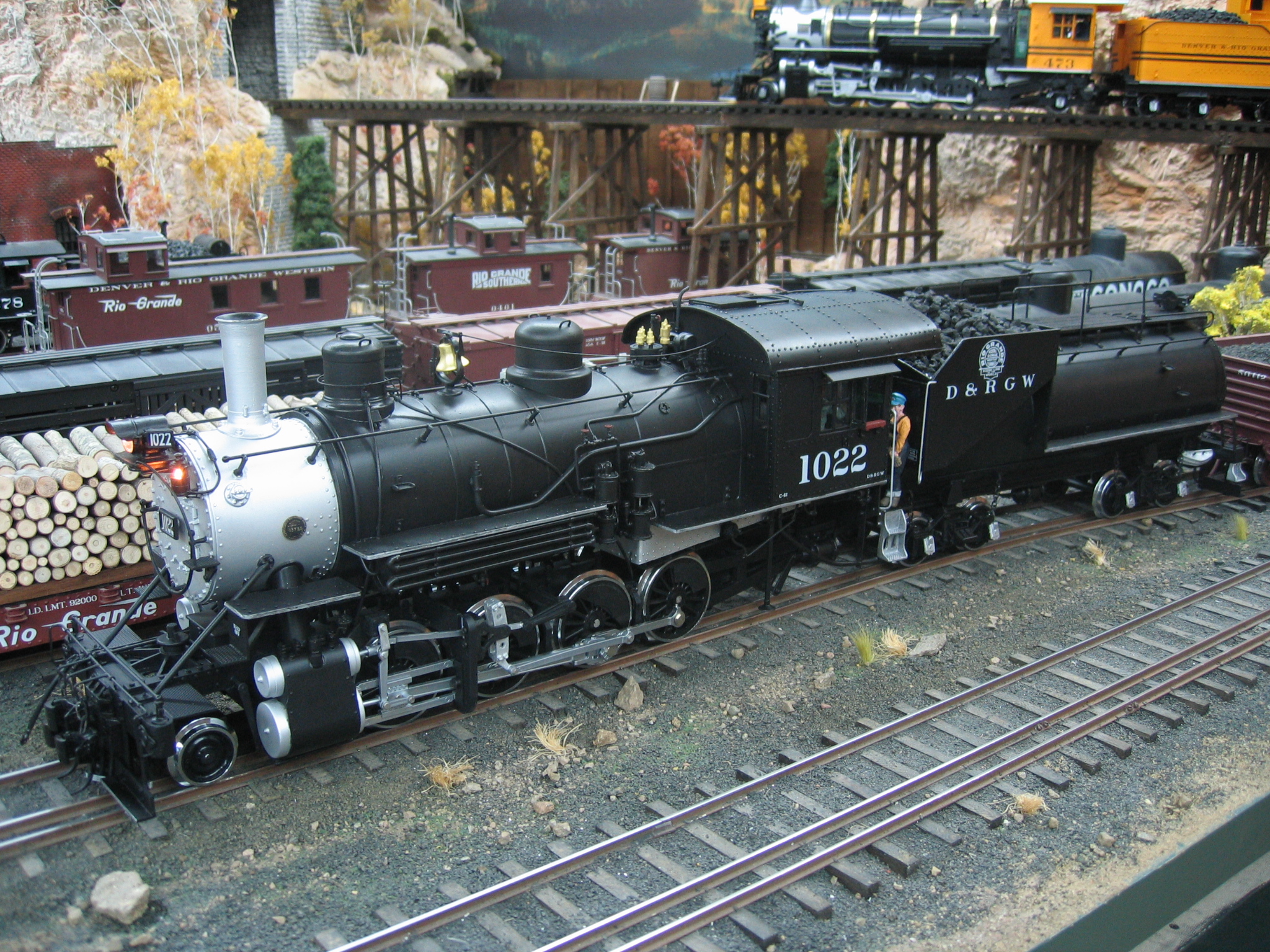
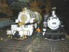
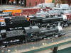
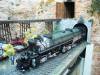
The Completed Locomotive
    During
the second week of September 2007, Barry painted and lettered the
C-41. He writes about this final phase of the project: "I
really like the Vanderbilt tender on this engine, as it it is
something different. I also used a crew from
Woodland Scenics for this engine, instead of the same old
guys as are in my other engines. The Woodland Scenics guys are
already painted, so I guess it was instant gratification for me, if
there is such a thing. The sound system is still mounted in the
tender, but the speaker is in the firebox of the engine. Sounds good
to me". During
the second week of September 2007, Barry painted and lettered the
C-41. He writes about this final phase of the project: "I
really like the Vanderbilt tender on this engine, as it it is
something different. I also used a crew from
Woodland Scenics for this engine, instead of the same old
guys as are in my other engines. The Woodland Scenics guys are
already painted, so I guess it was instant gratification for me, if
there is such a thing. The sound system is still mounted in the
tender, but the speaker is in the firebox of the engine. Sounds good
to me".
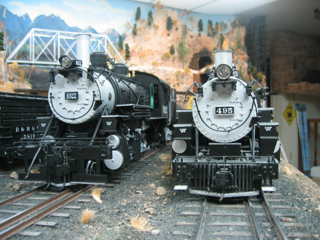
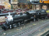
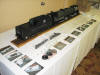
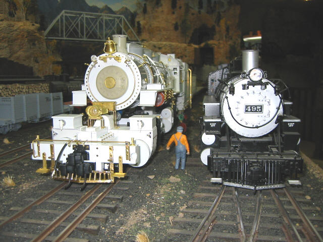
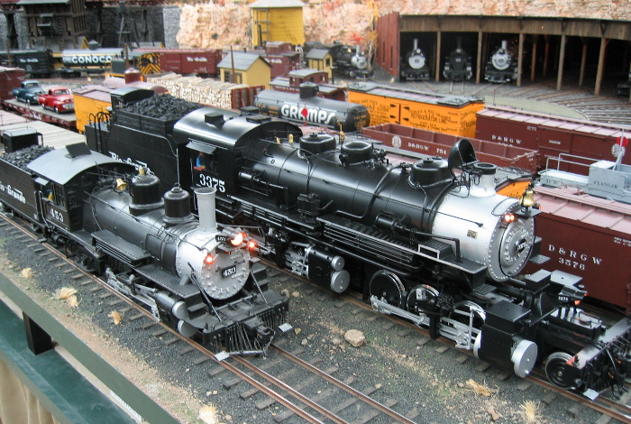
Barry also took a
series of shots comparing the C-41 to his model of the C-41's narrow
gauge successor, the D&RGW's K-37 2-8-2. Barry remarks about the
differences between the C-41 and the K-37:
      As
most of you know, the K-37 NG engines were built from the C-41
SG engines by the Grande in 1928-1930 in the Denver shops. All
of the K-37s had the box type tender, and not the Vandy one that
I modeled. All of the C-41's with the Vandy tender were
scrapped. I still thought it would be neat to see the engines
side by side and compare them. Again, all I had for a plan for
the engine is the two pictures at left, and an O scale model of
the D&RGW's C-48 2-8-0,
so I may be a little off on my dimensions. As you can see, the
K-37 has a longer smoke box and a smaller cab than the C-41. The
reason for this is when the D&RGW lowered the C-41 boiler onto
the K-37's NG 2-8-2 chassis from Baldwin, the boiler had to be
moved back in order for the firebox to clear the rear set
of drivers (I had always wondered why I had so much cab swing on
the K-36 / K-37 class engines around my own curves!). Of course
the smoke box also had to be lengthened to fit the chassis, thus
the K-37 NG engine is longer the C-41 SG engine! From what I can
tell, the only thing that the Grande used from the C-41 was just
the boiler only, and fabricated everything else in the shop,
like the cab, rear frame extension, smoke box, etc. What a kit
bash. I had always wondered why the brass importers never
offered a model of the C-41 at the same time they made ones of
the K-37. Well, I understand now. It is almost a totally new
project! It has been a fun venture, but has it has had its
moments with no real plan to work from. My best work comes from
having an O scale model, 1:22.5 scale plans, and many pictures
from which to work from. This project had few. You decide if the
C-41 is on the money or not--I won't be offended if you think
not. I hope to do an article on the conversion some time, but
for now enjoy what I have come up. As
most of you know, the K-37 NG engines were built from the C-41
SG engines by the Grande in 1928-1930 in the Denver shops. All
of the K-37s had the box type tender, and not the Vandy one that
I modeled. All of the C-41's with the Vandy tender were
scrapped. I still thought it would be neat to see the engines
side by side and compare them. Again, all I had for a plan for
the engine is the two pictures at left, and an O scale model of
the D&RGW's C-48 2-8-0,
so I may be a little off on my dimensions. As you can see, the
K-37 has a longer smoke box and a smaller cab than the C-41. The
reason for this is when the D&RGW lowered the C-41 boiler onto
the K-37's NG 2-8-2 chassis from Baldwin, the boiler had to be
moved back in order for the firebox to clear the rear set
of drivers (I had always wondered why I had so much cab swing on
the K-36 / K-37 class engines around my own curves!). Of course
the smoke box also had to be lengthened to fit the chassis, thus
the K-37 NG engine is longer the C-41 SG engine! From what I can
tell, the only thing that the Grande used from the C-41 was just
the boiler only, and fabricated everything else in the shop,
like the cab, rear frame extension, smoke box, etc. What a kit
bash. I had always wondered why the brass importers never
offered a model of the C-41 at the same time they made ones of
the K-37. Well, I understand now. It is almost a totally new
project! It has been a fun venture, but has it has had its
moments with no real plan to work from. My best work comes from
having an O scale model, 1:22.5 scale plans, and many pictures
from which to work from. This project had few. You decide if the
C-41 is on the money or not--I won't be offended if you think
not. I hope to do an article on the conversion some time, but
for now enjoy what I have come up.
|
|
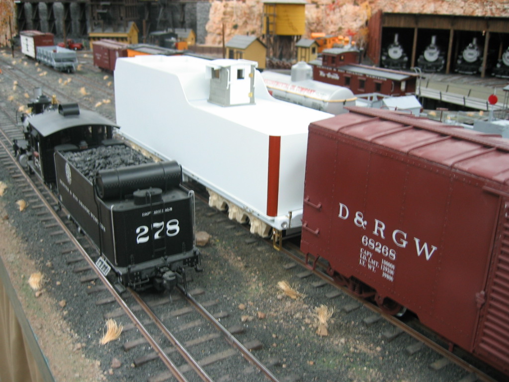
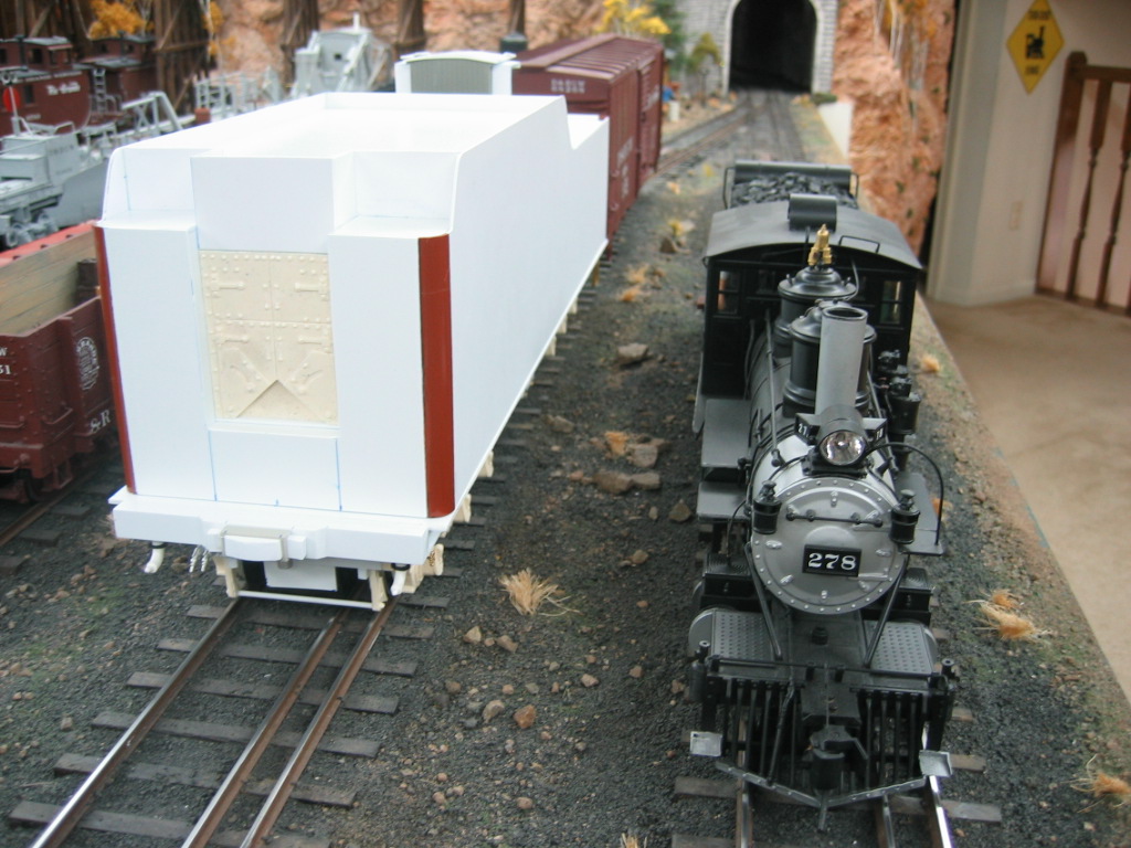
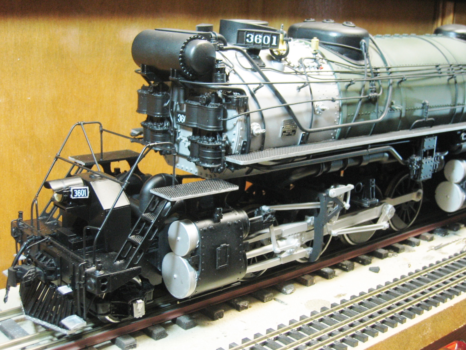
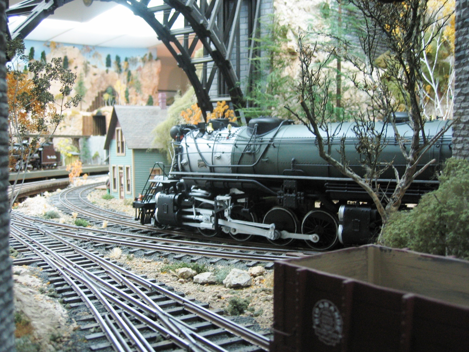
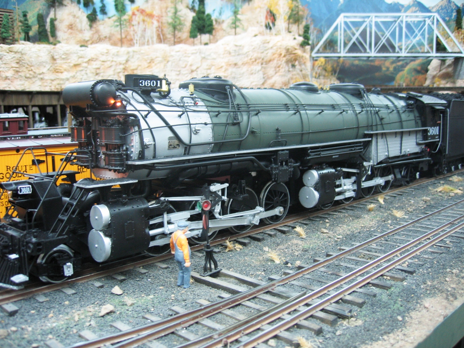
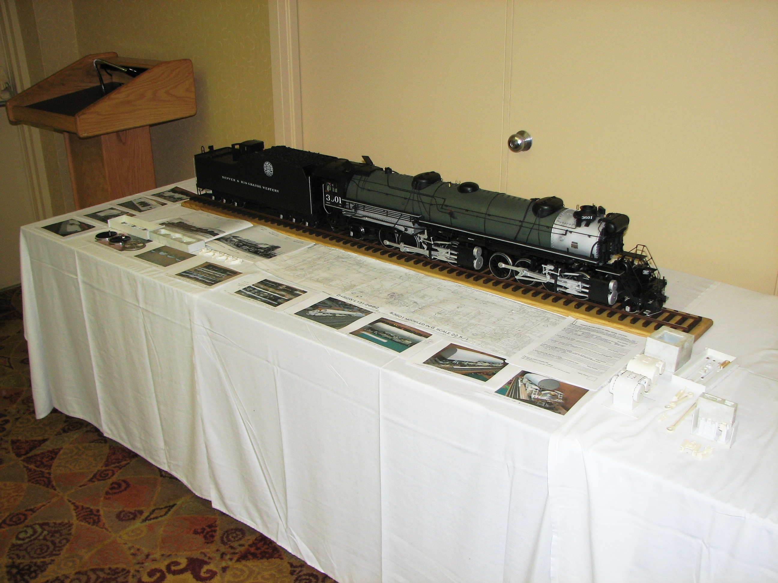
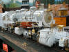
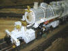
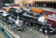
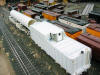
 D&RGW
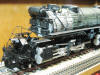
L-131 2-8-8-2 D&RGW
L-131 2-8-8-2
(2007-2008)
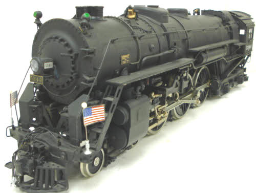
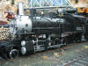
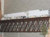
Built by Alco in 1927, the L-131
2-8-8-2 was the D&RGW's largest and most powerful class of steam
locomotive, measuring 120 feet long from pilot to tender, 11'-8"
wide, and 16'-1˝" tall; and boasting 131,800 lbs. of tractive
effort from its 63” drivers. Each tender carried 30 tons coal and
18,000 gallons of water. Walschaert valve gear was original
equipment on both the 3600-3609 series L-131, and the 3610-3619
series L-132 built a few years later in 1930. Like all D&RGW standard
gauge steam, save for a lowly slide valve C-28 2-8-0 of 19th century
vintage, the L-131s were retired and scraped, mainly over the period
1955-1956, having been replaced by FTs initially and then other EMD
"covered wagon" first generation diesels.
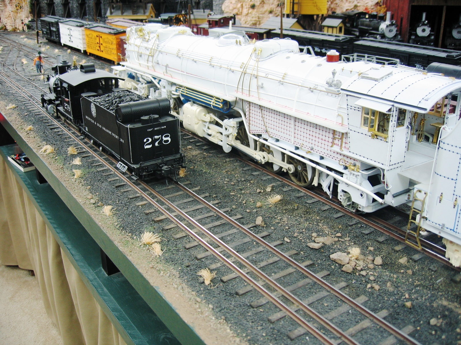
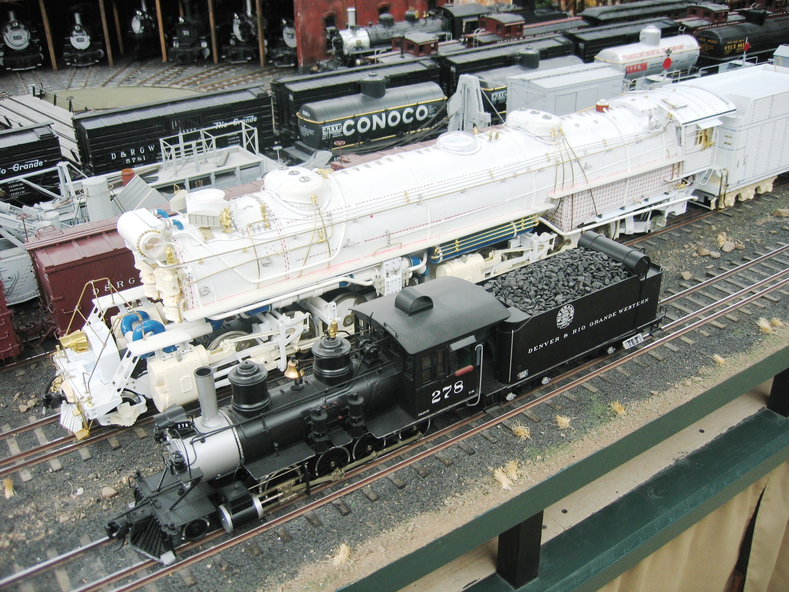
Barry's 1:22.5 scale, Gauge 3 model is powered by modified LGB
Mikado drive units using custom made white bronze drivers, but with
LGB wheels on all other axles. When complete, the engine and tender
will measure 64” long and be capable of negotiating a 5' foot
minimum radius curve. A Digitrax decoder and Phoenix 2K2 sound will
be mounted in the tender. |
|
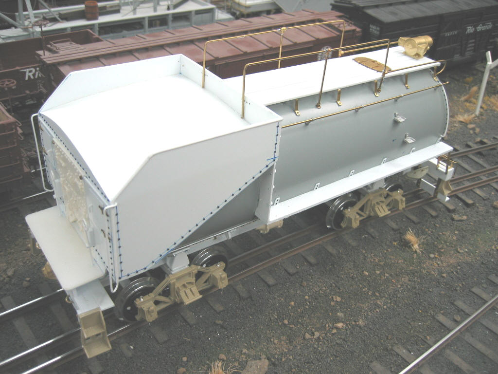
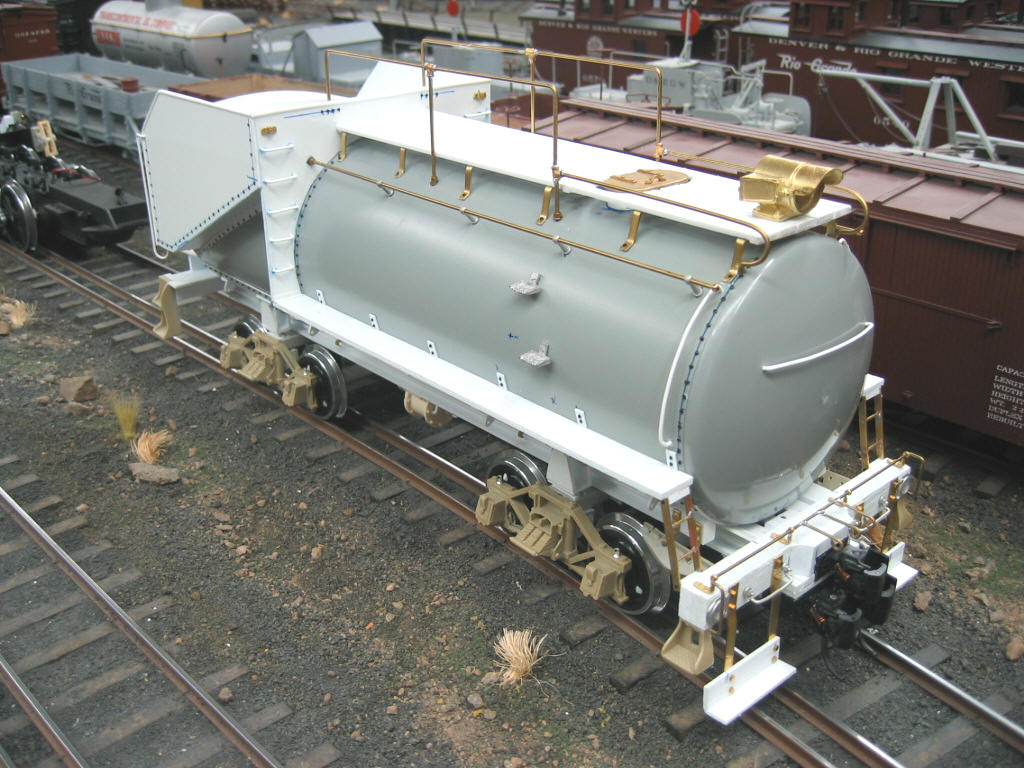
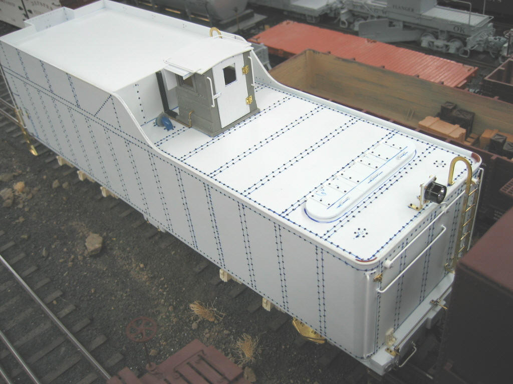
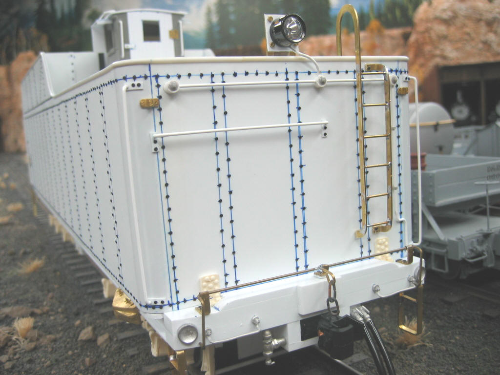
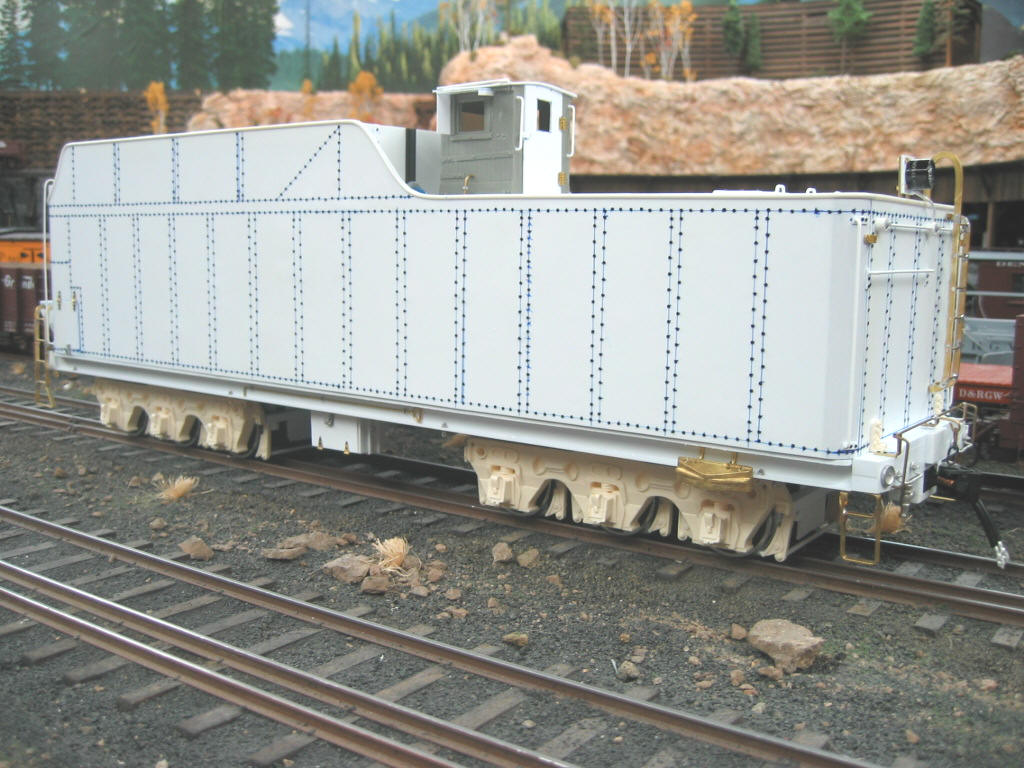
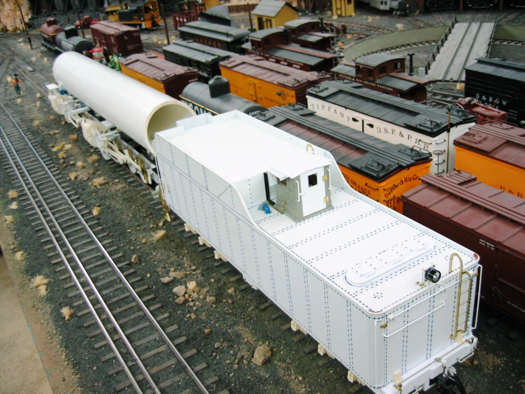
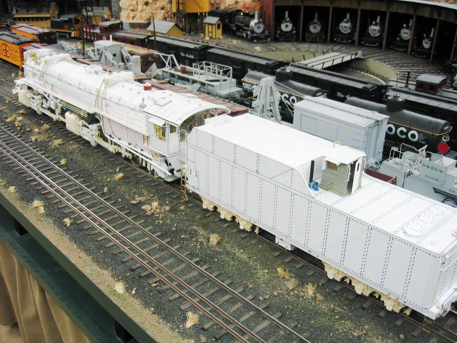
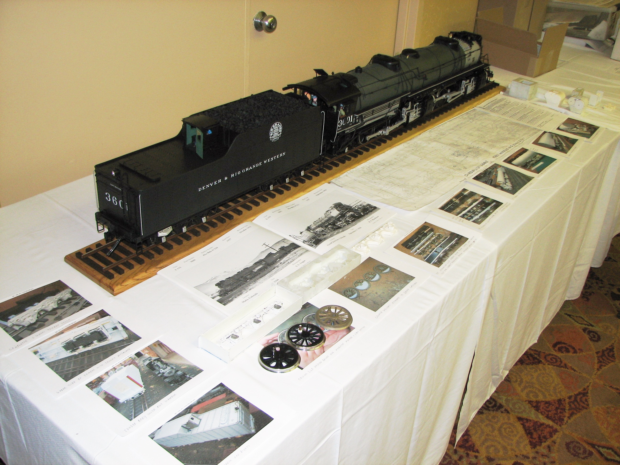
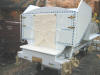
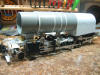
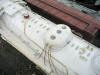
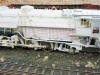
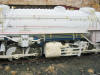
The Tender


 |
|
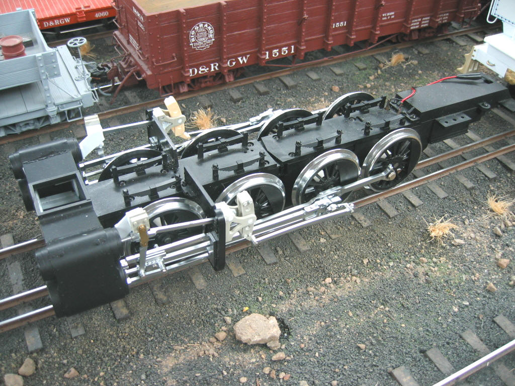
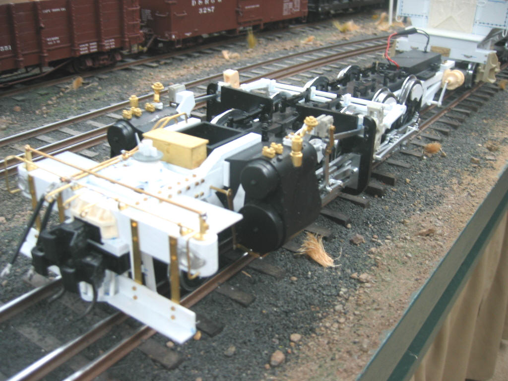
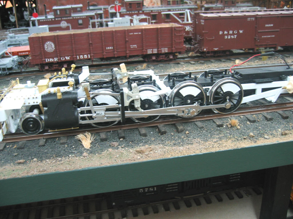
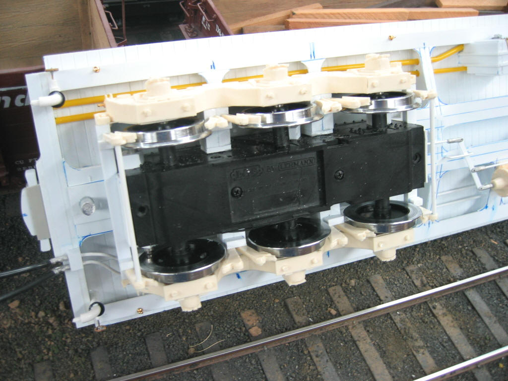
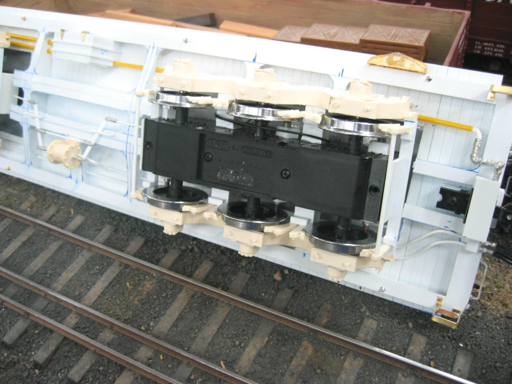
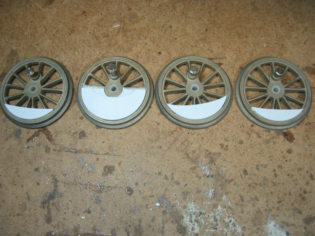
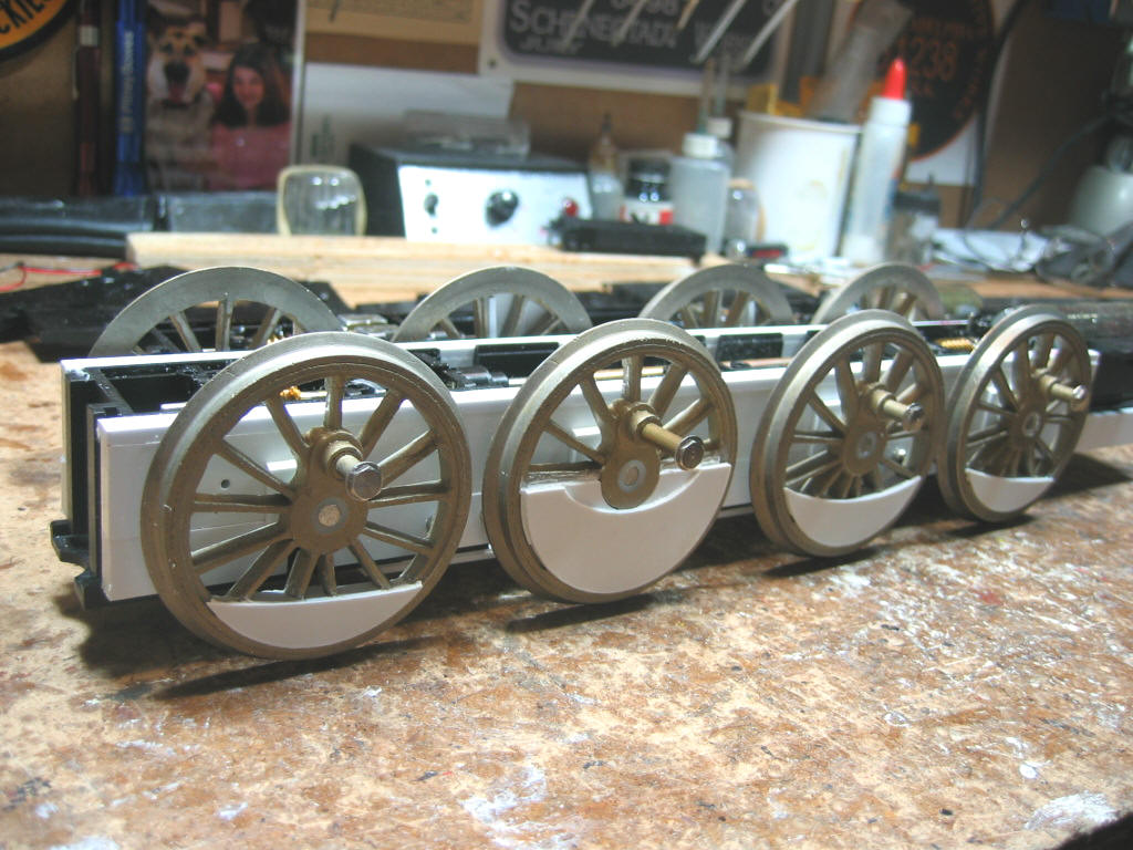
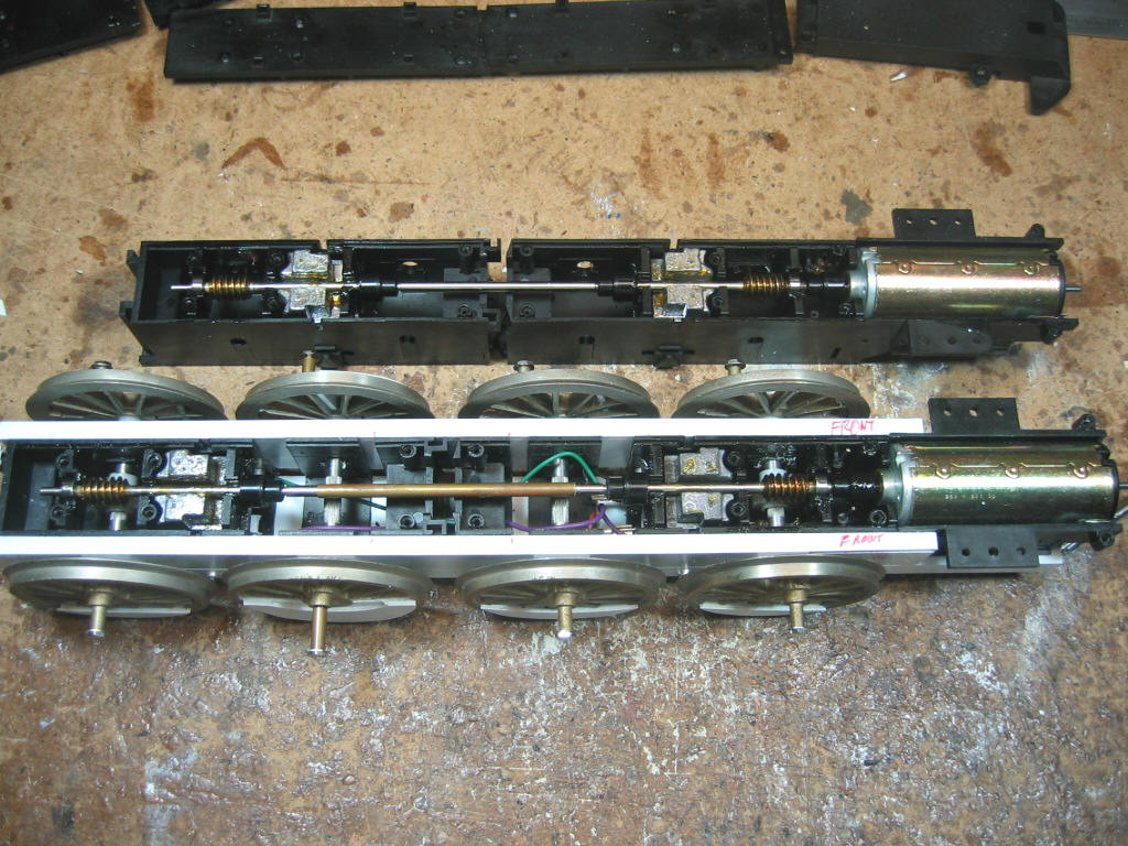
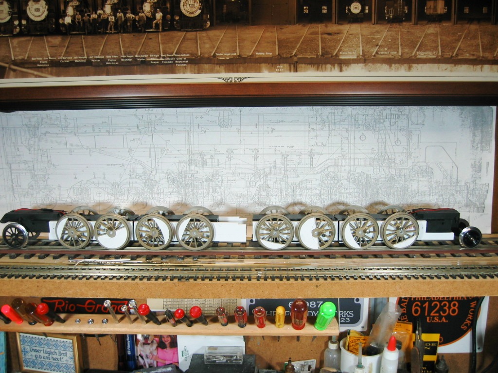
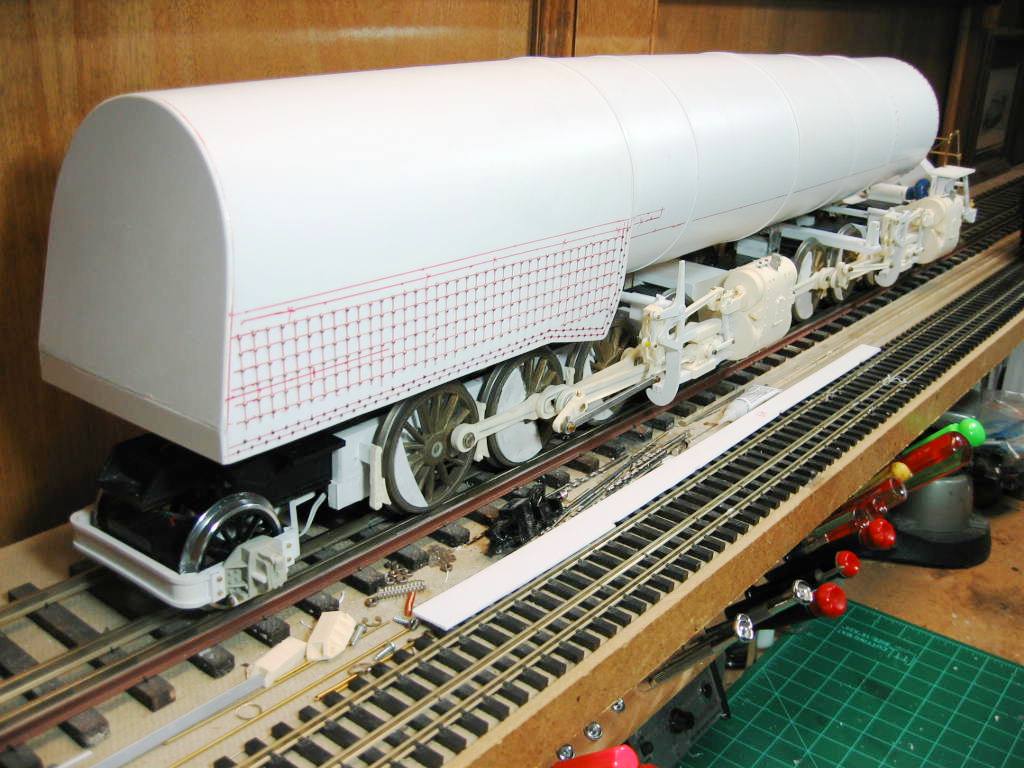
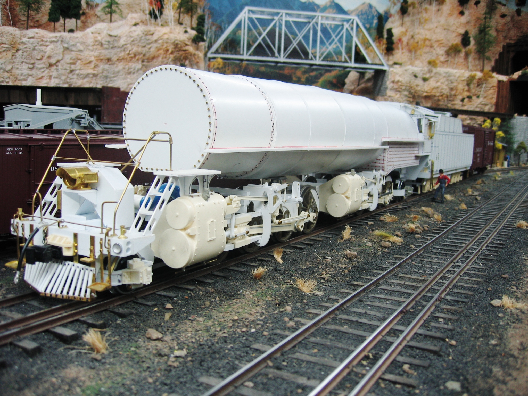
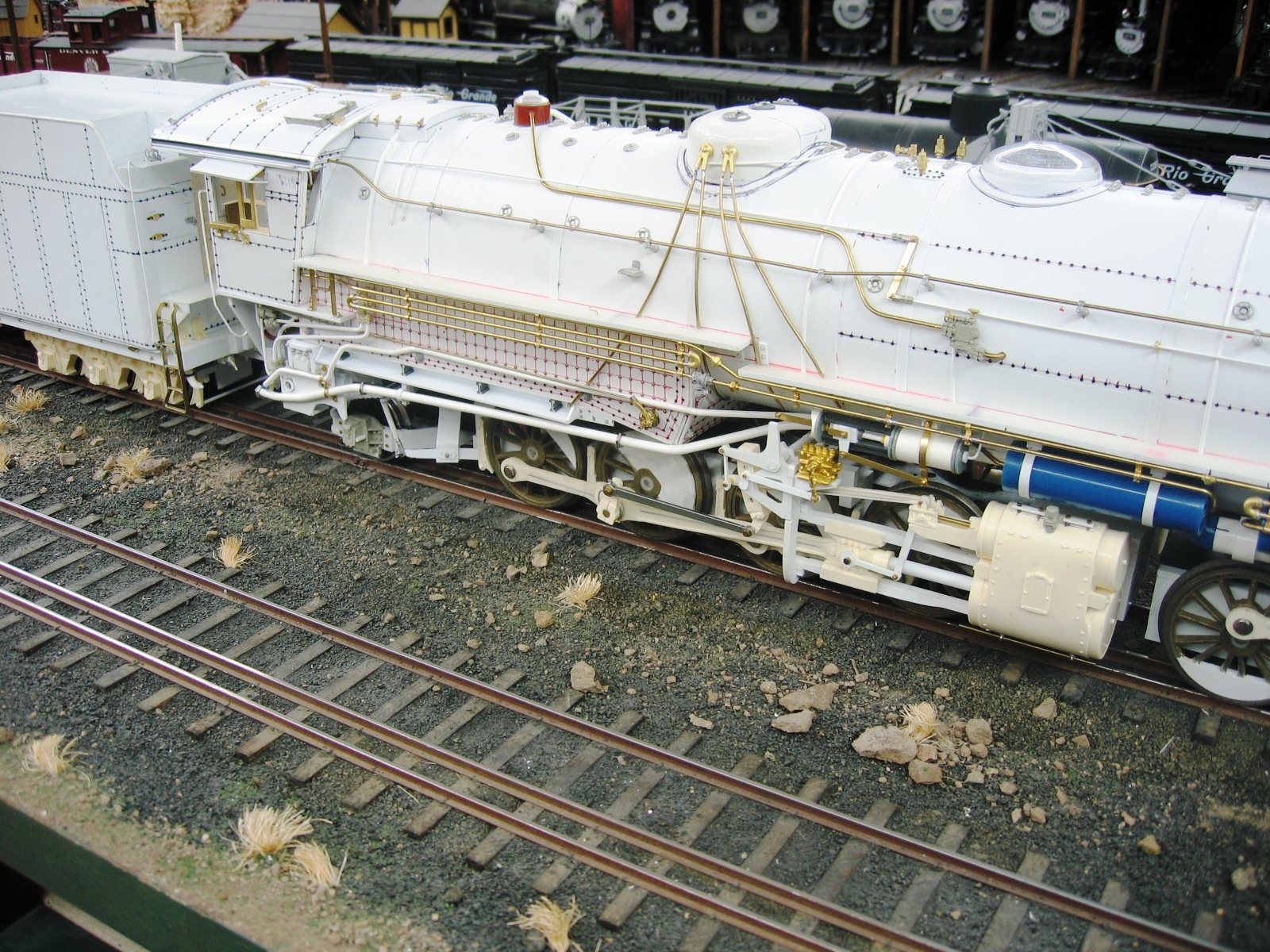
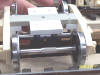
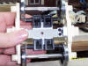
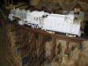
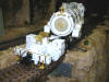
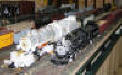
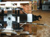
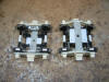
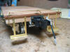
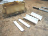
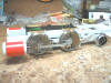
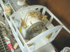
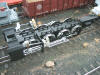
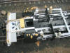
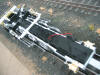
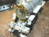
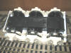
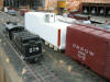
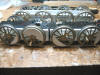
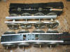
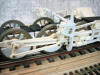
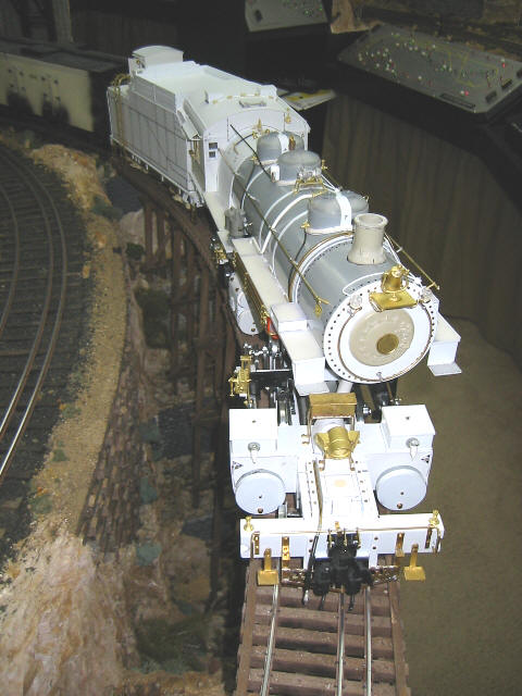
The Chassis & Drivers
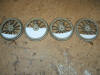  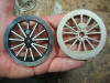 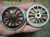   One
of the first issues for Barry to settle in planning the construction
of the Gauge 3 L-131 2-8-8-2 was where to find suitable drivers.
Nothing in the usual LGB or other Gauge 1 product lines even
remotely approached the large 2.8" diameter spoked drivers he would
need, that is, with one exception. The drivers for Barry's L-131
do have an LGB origin of sorts: Several years ago, LGB
commissioned Aster of Japan to build a series of limited production
NYC J1e 4-6-4s in Gauge 1. Barry was able to acquire several spare
drivers from one of these locos and to modify its center from a
boxpok to a spoked configuration. With the addition of crankpins,
Barry's modified driver became a casting pattern. Yet another Texan,
Dennis Mashburn (of K & D
Castings) produced white bronze investment castings from Barry's
master and then machined the tread on each of the drivers. Barry did
not use separate tyres on these drivers; rather, insulation is
accomplished using a delrin bushing on the shouldered end of each
6mm Gauge 3 axle. The end of each axle is knurled, the bushings are
themselves machined for a .001" on the radius interference fit, and
then the bushings have red
Loctite applied to them before
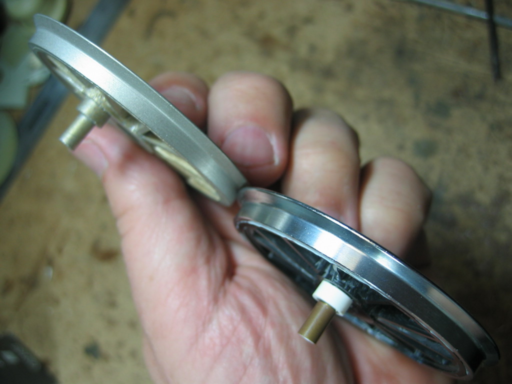
being pressed into each driver. One
of the first issues for Barry to settle in planning the construction
of the Gauge 3 L-131 2-8-8-2 was where to find suitable drivers.
Nothing in the usual LGB or other Gauge 1 product lines even
remotely approached the large 2.8" diameter spoked drivers he would
need, that is, with one exception. The drivers for Barry's L-131
do have an LGB origin of sorts: Several years ago, LGB
commissioned Aster of Japan to build a series of limited production
NYC J1e 4-6-4s in Gauge 1. Barry was able to acquire several spare
drivers from one of these locos and to modify its center from a
boxpok to a spoked configuration. With the addition of crankpins,
Barry's modified driver became a casting pattern. Yet another Texan,
Dennis Mashburn (of K & D
Castings) produced white bronze investment castings from Barry's
master and then machined the tread on each of the drivers. Barry did
not use separate tyres on these drivers; rather, insulation is
accomplished using a delrin bushing on the shouldered end of each
6mm Gauge 3 axle. The end of each axle is knurled, the bushings are
themselves machined for a .001" on the radius interference fit, and
then the bushings have red
Loctite applied to them before
being pressed into each driver.
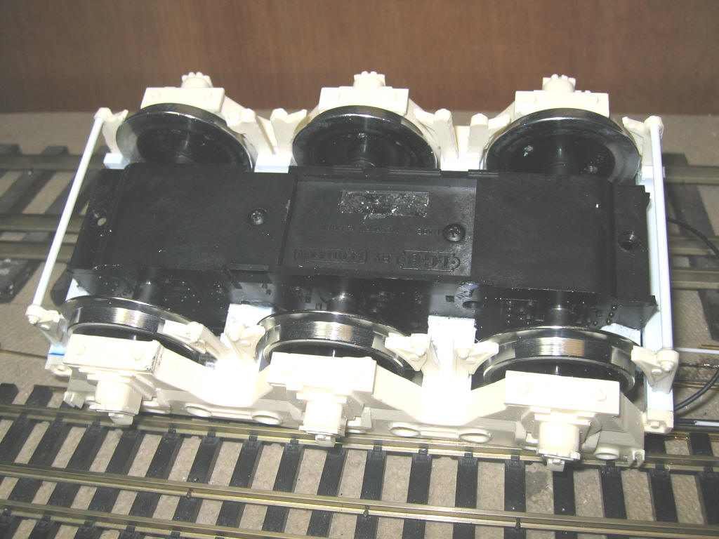
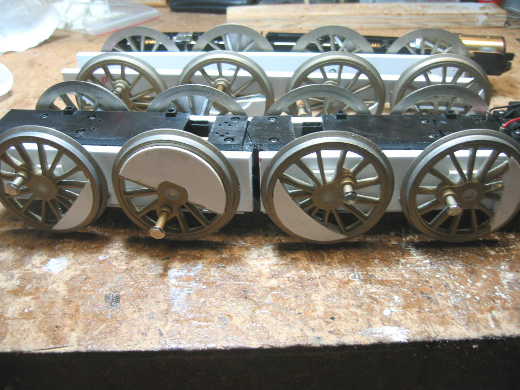
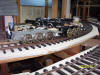
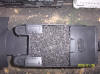
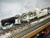
 For
the mechanism of the L-131, Barry is using two regauged LGB Mikado
motor blocks which have themselves been extensively modified with
respect to their wheelbase. With a hinge in each motor block, and
then two motor blocks per locomotive which are themselves mounted
independent of each other, though slung beneath one boiler, Barry is
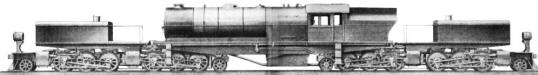
in effect building in mini- For
the mechanism of the L-131, Barry is using two regauged LGB Mikado
motor blocks which have themselves been extensively modified with
respect to their wheelbase. With a hinge in each motor block, and
then two motor blocks per locomotive which are themselves mounted
independent of each other, though slung beneath one boiler, Barry is
in effect building in mini- ature the proposed Beyer Peacock Quadruplex 2-6-6-2+2-6-6-2 (or "Super Garratt" is it has sometimes
been called) that was seriously offered by Beyer-Peacock in 1927.
Barry describes the conversion process in his own words: ature the proposed Beyer Peacock Quadruplex 2-6-6-2+2-6-6-2 (or "Super Garratt" is it has sometimes
been called) that was seriously offered by Beyer-Peacock in 1927.
Barry describes the conversion process in his own words:
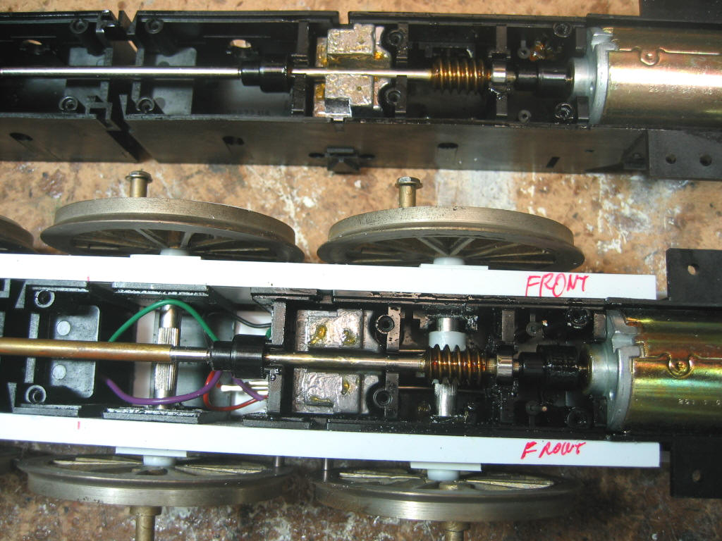
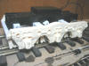
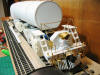
"It
was time to slice into the LGB Mikado motor block to lengthen it to
accept the larger L131 drivers. I milled out some 1/4 X 3/4 plastic
bar stock for the main frames to hold the drivers at the correct
spacing. I then cut the motor block in four places to stretch it
out. Next, I glued both main frames to the side of the motor end of
the motor block. I then glued the short sections of the second and
third driver axles, to the main frames. The hinge section was
attached together and glued into the frame assembly, and last I
added the other end between the main frames. I added spacers to keep
the axles centered, and lengthened the drive tube between the two
worm gears. I had to move the electrical pick ups from the original
location, to meet the new wheels. New wiring wrapped up the loose
ends and got the motor some power. It ran on the straight track of
the test track OK, but the layout will tell the truth. I cut both
sides of the main frame next, on both sides and this allows the
motor block to flex on the curves and turnouts. After a few
adjustments with the wheel gauge and the hinge gap, it ran great.
This is the start of the front engine. Hope to get the rear engine
up to this point soon. The pictures above and below show the original block next to
the modified one, just for reference."


 |
|
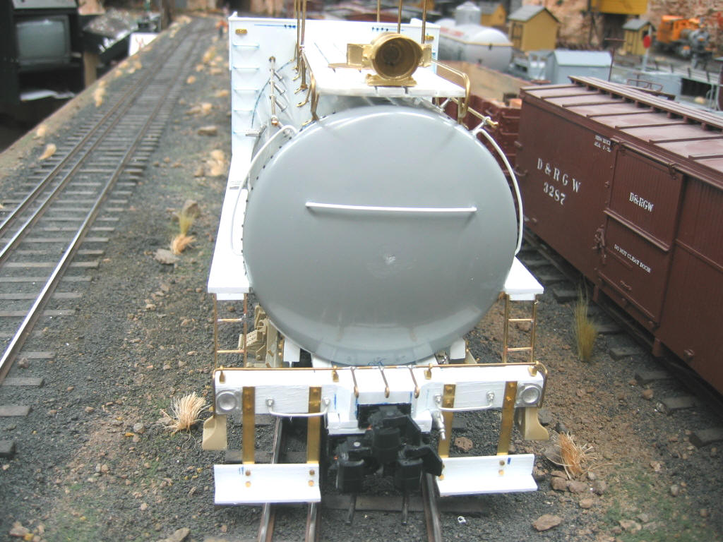
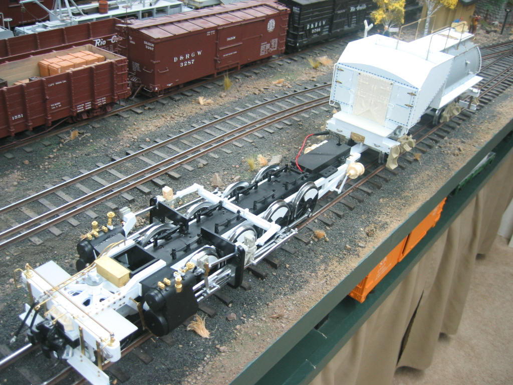
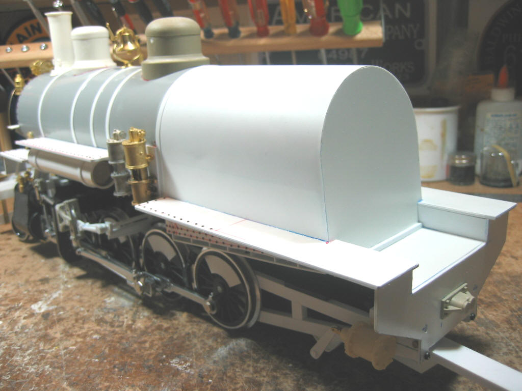
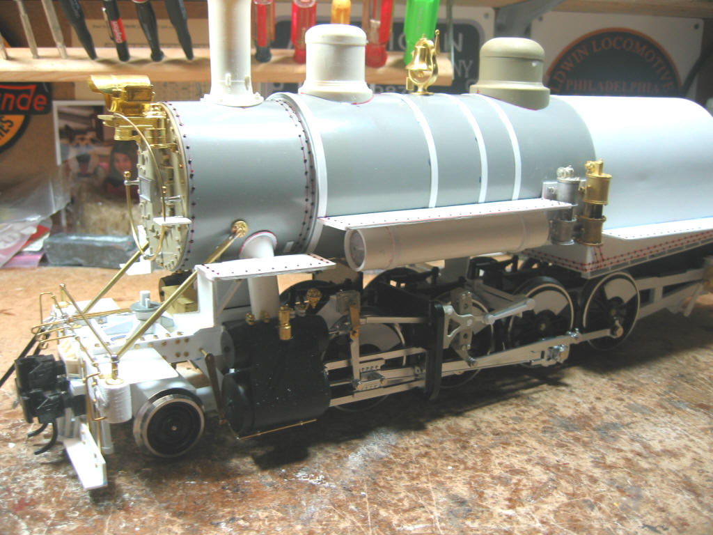
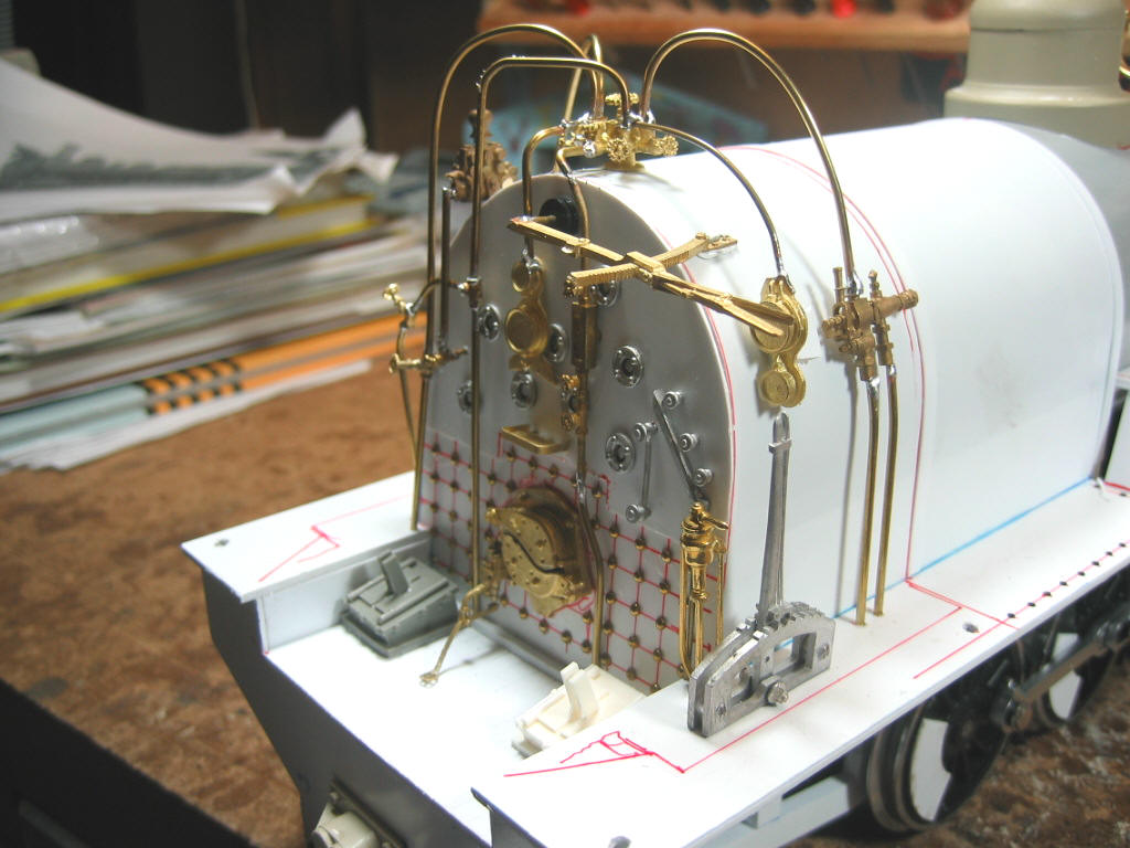
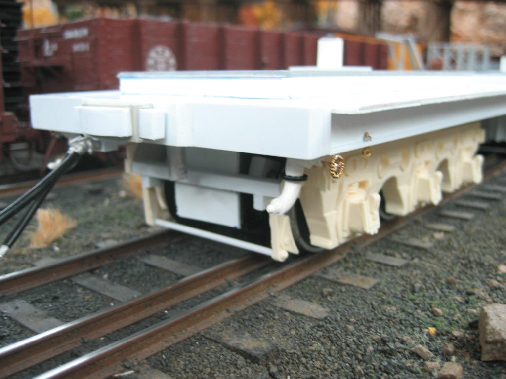
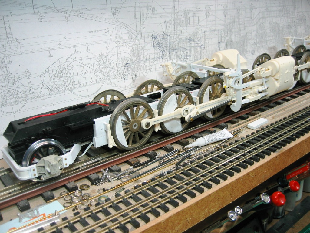
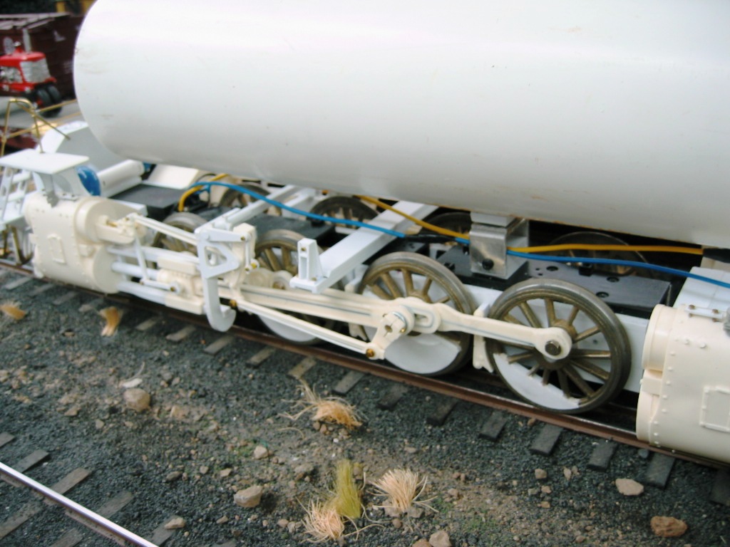
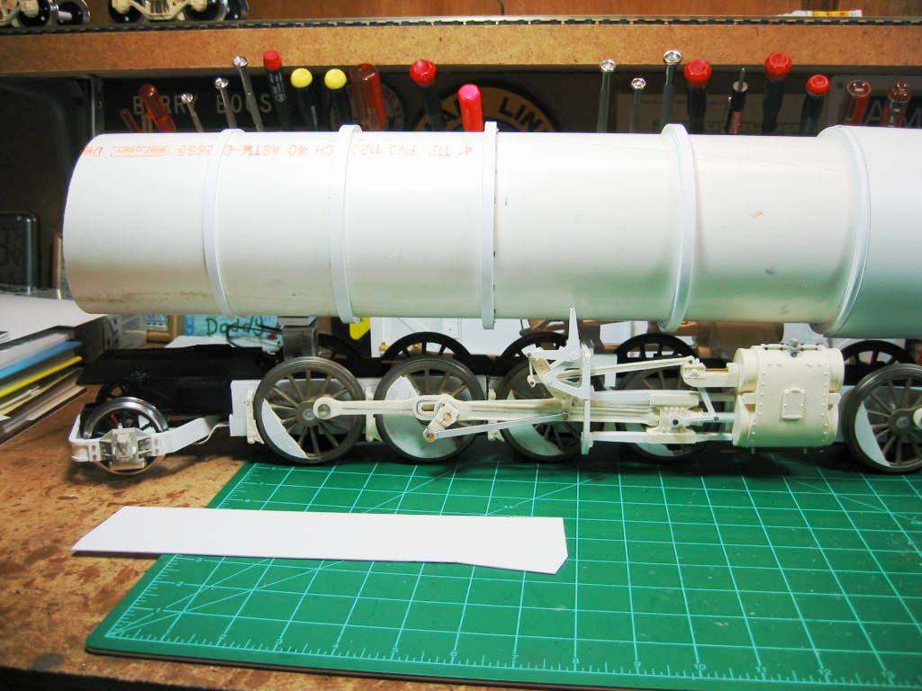
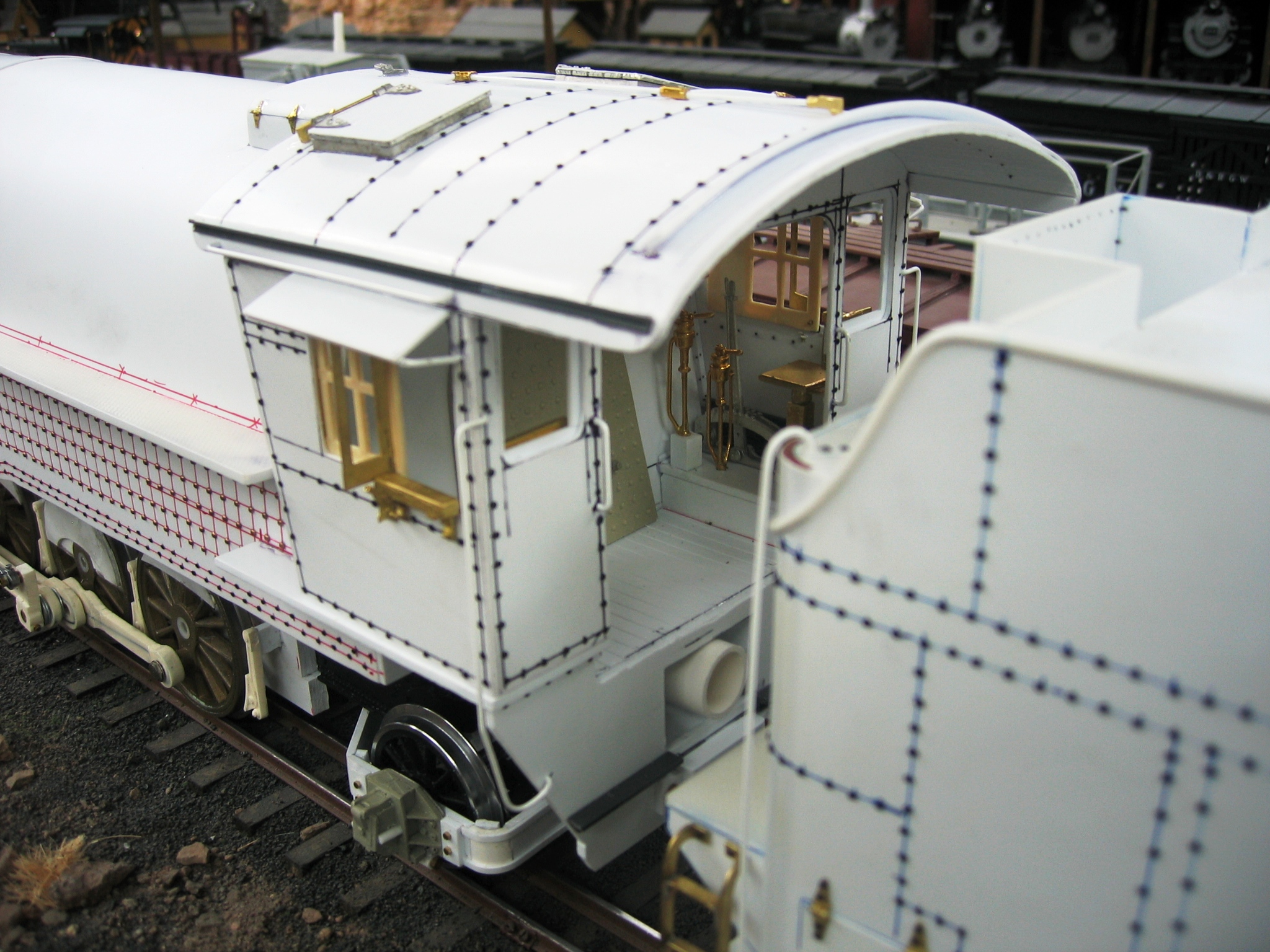
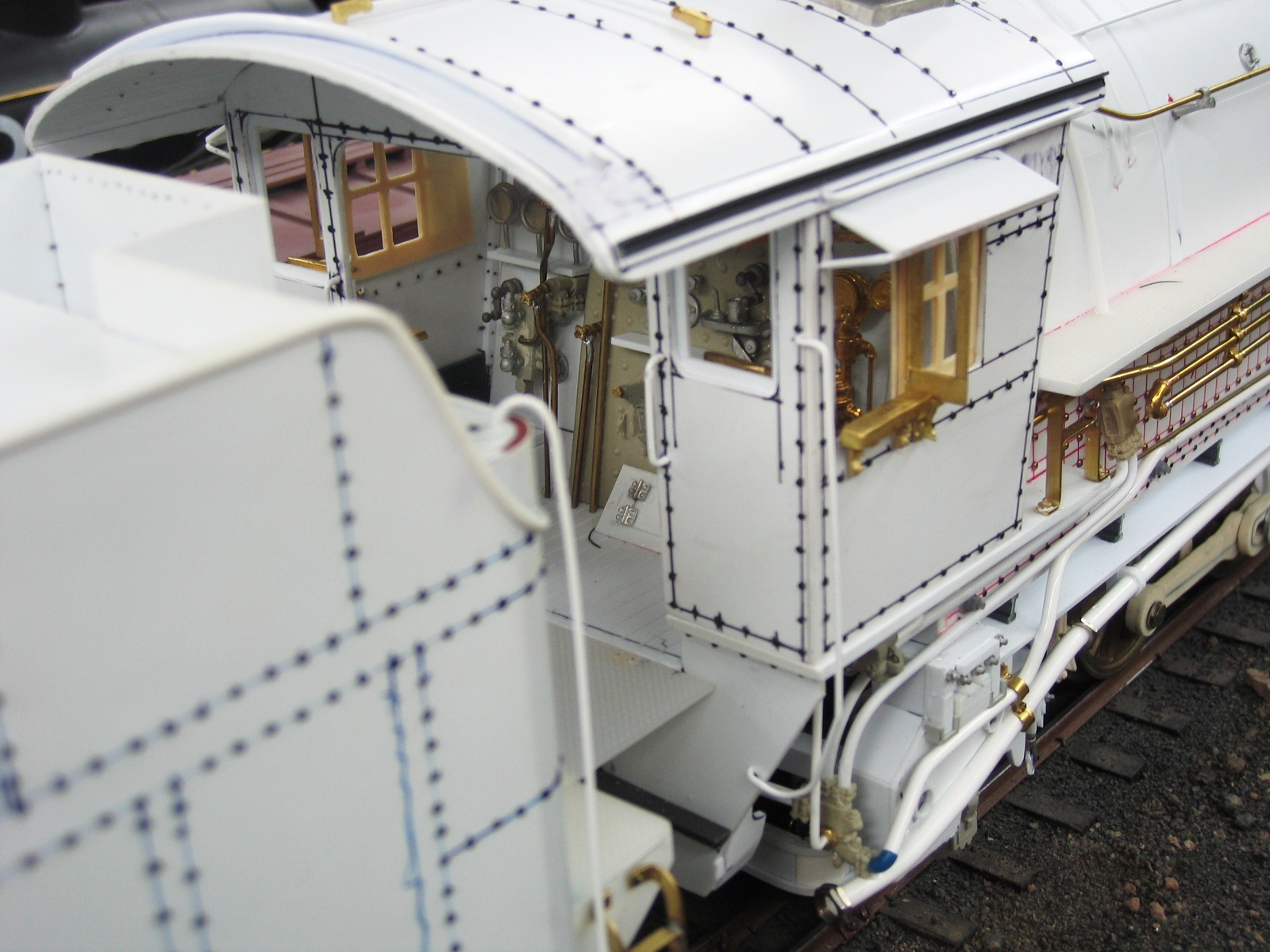
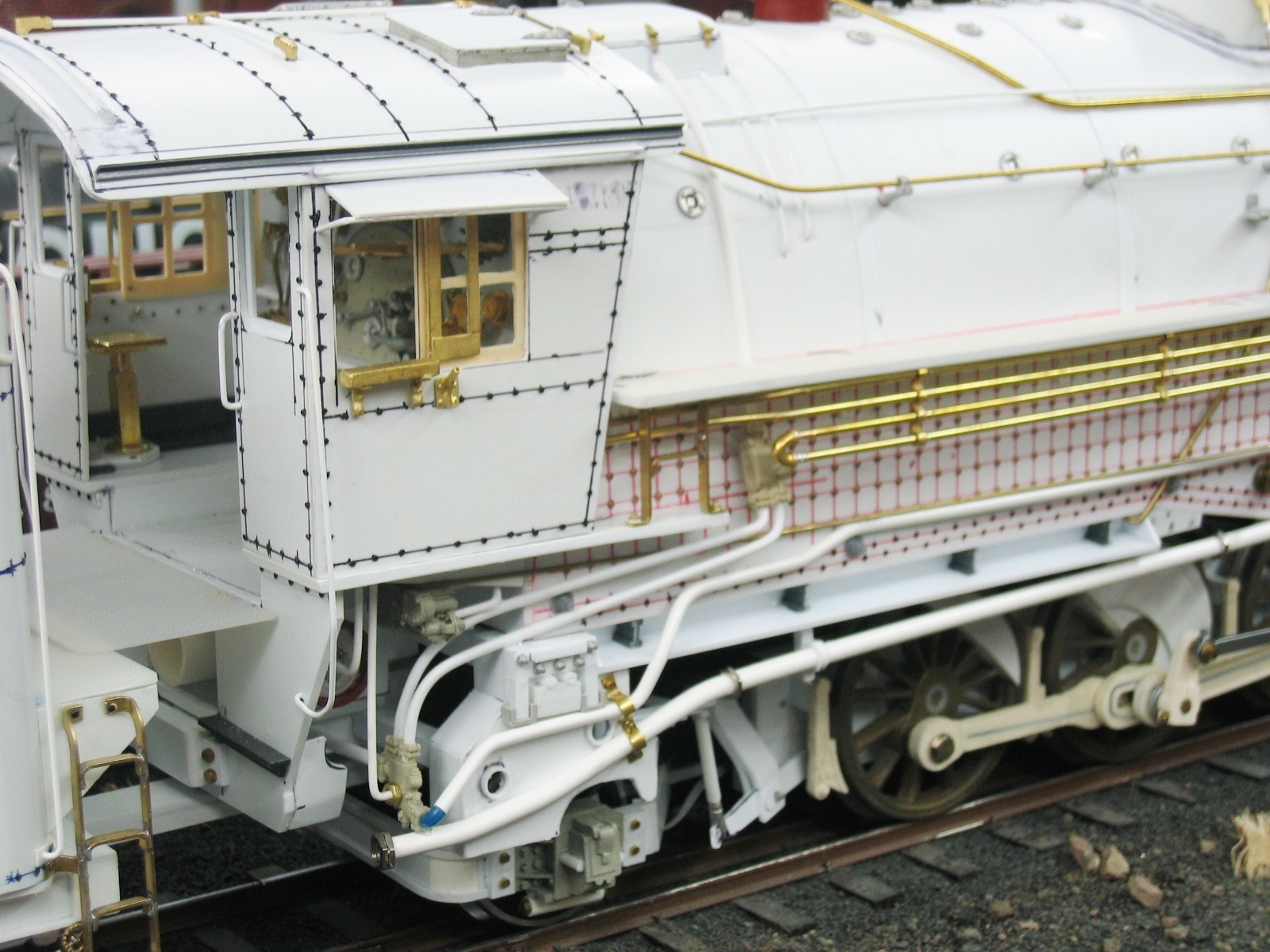
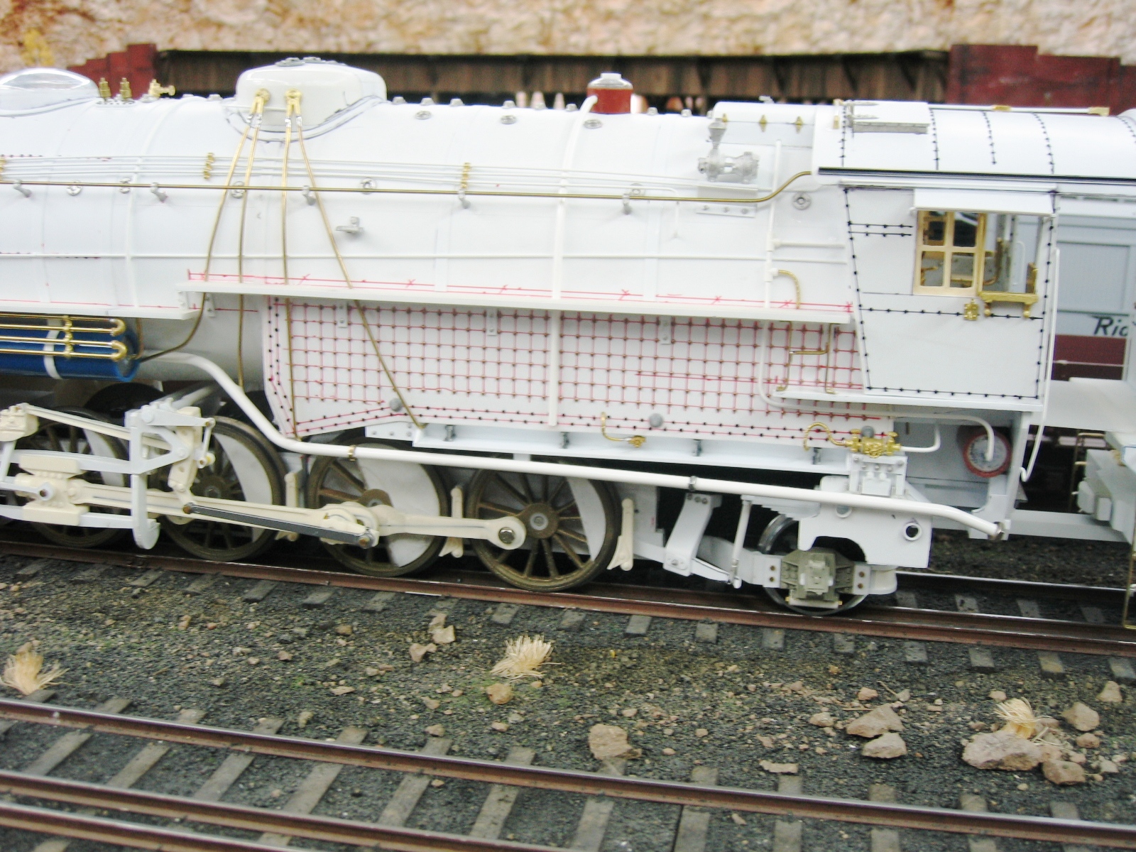
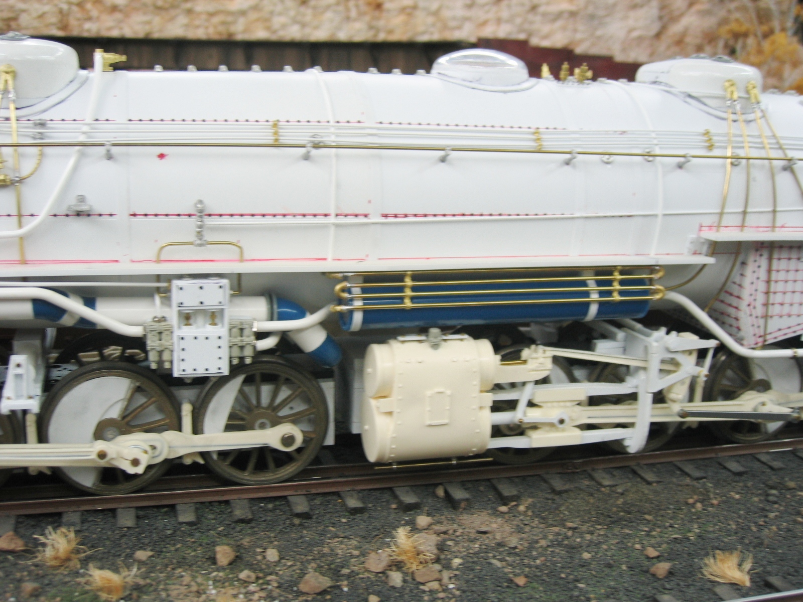
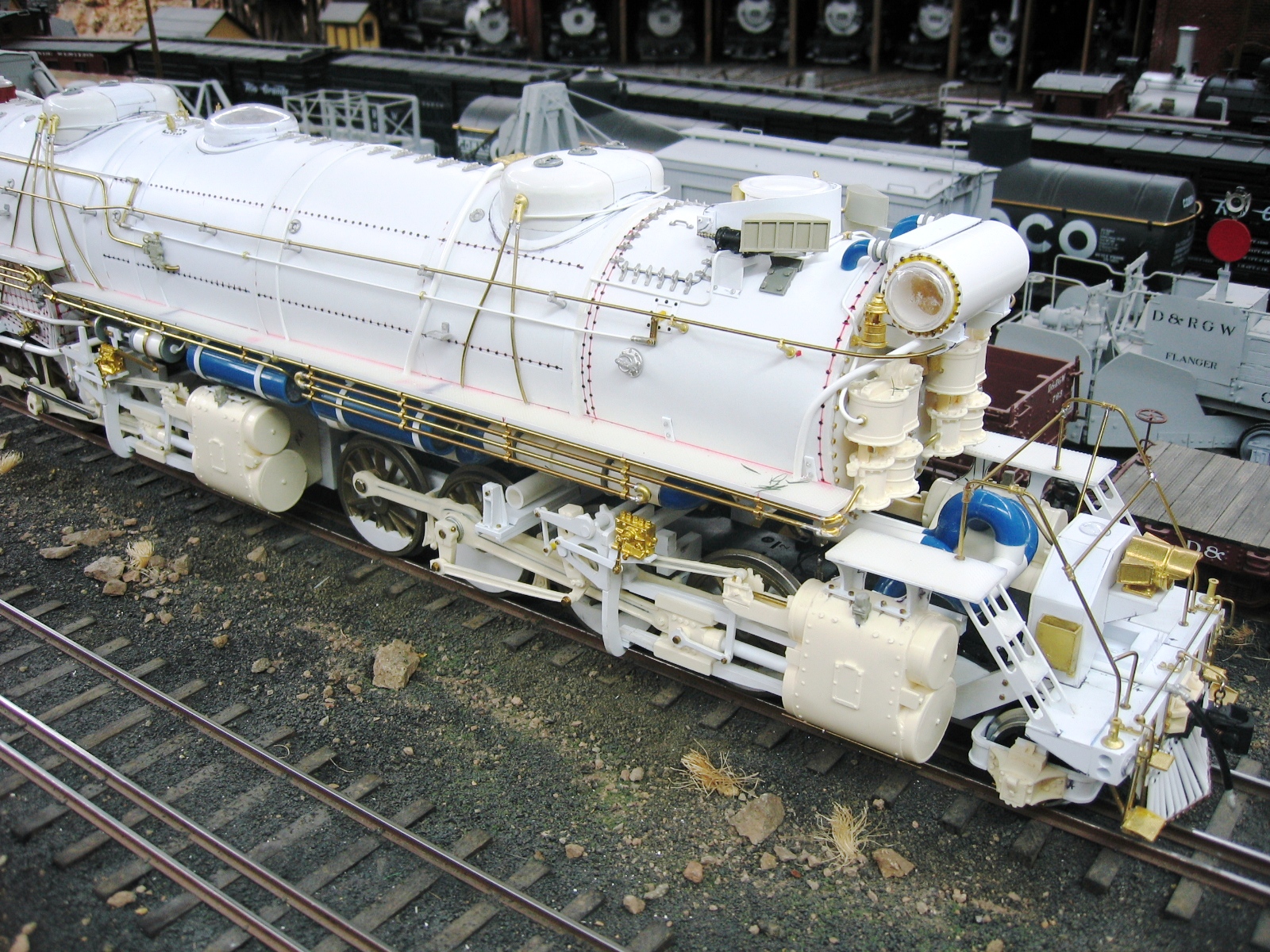
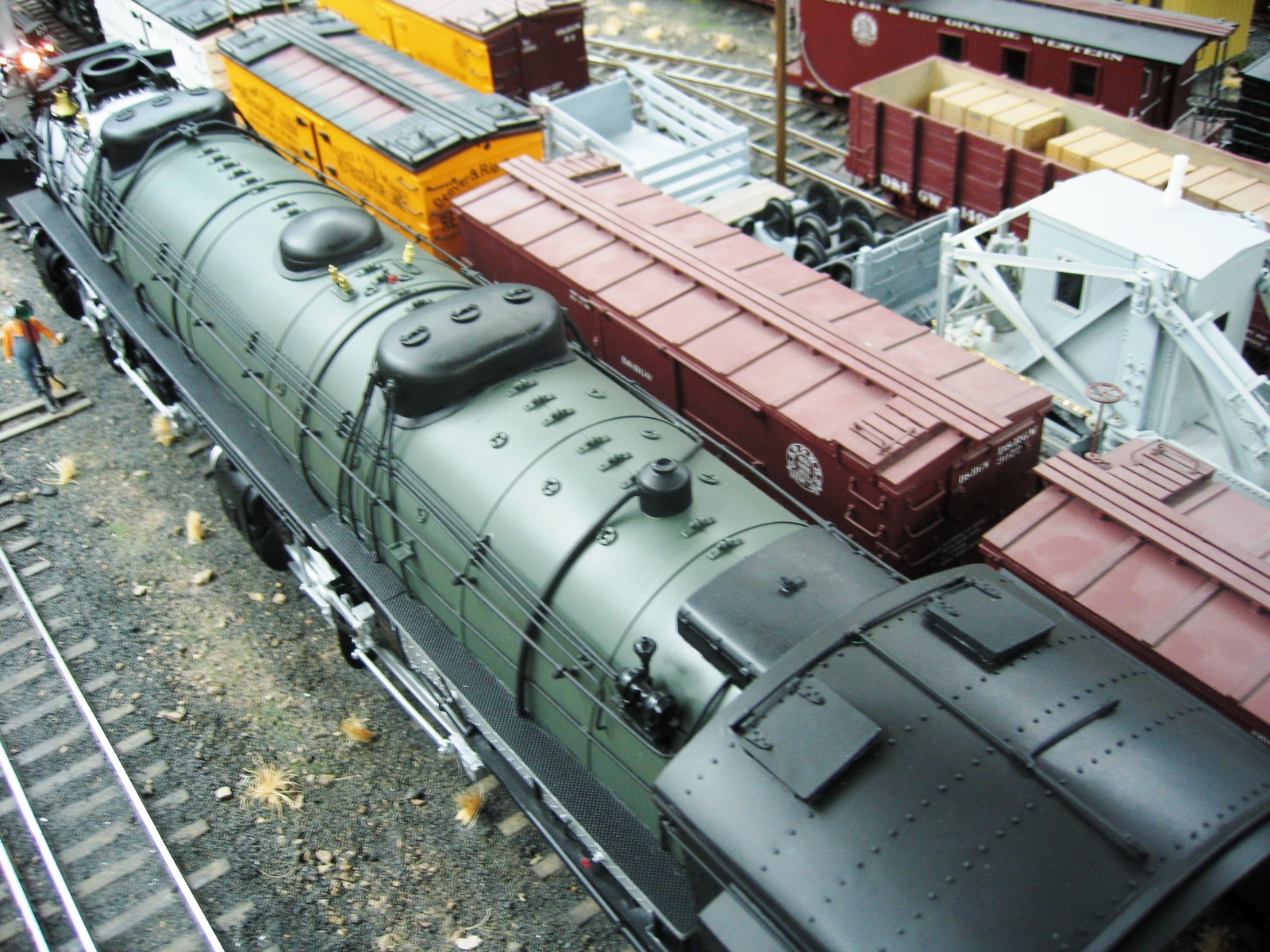
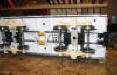
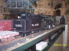
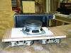
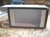
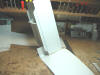
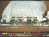
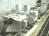
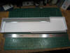
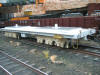
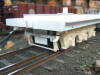
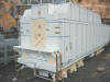
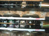
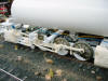
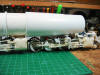
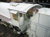
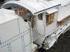
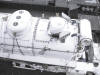
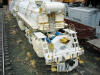
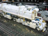
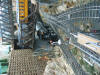
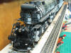
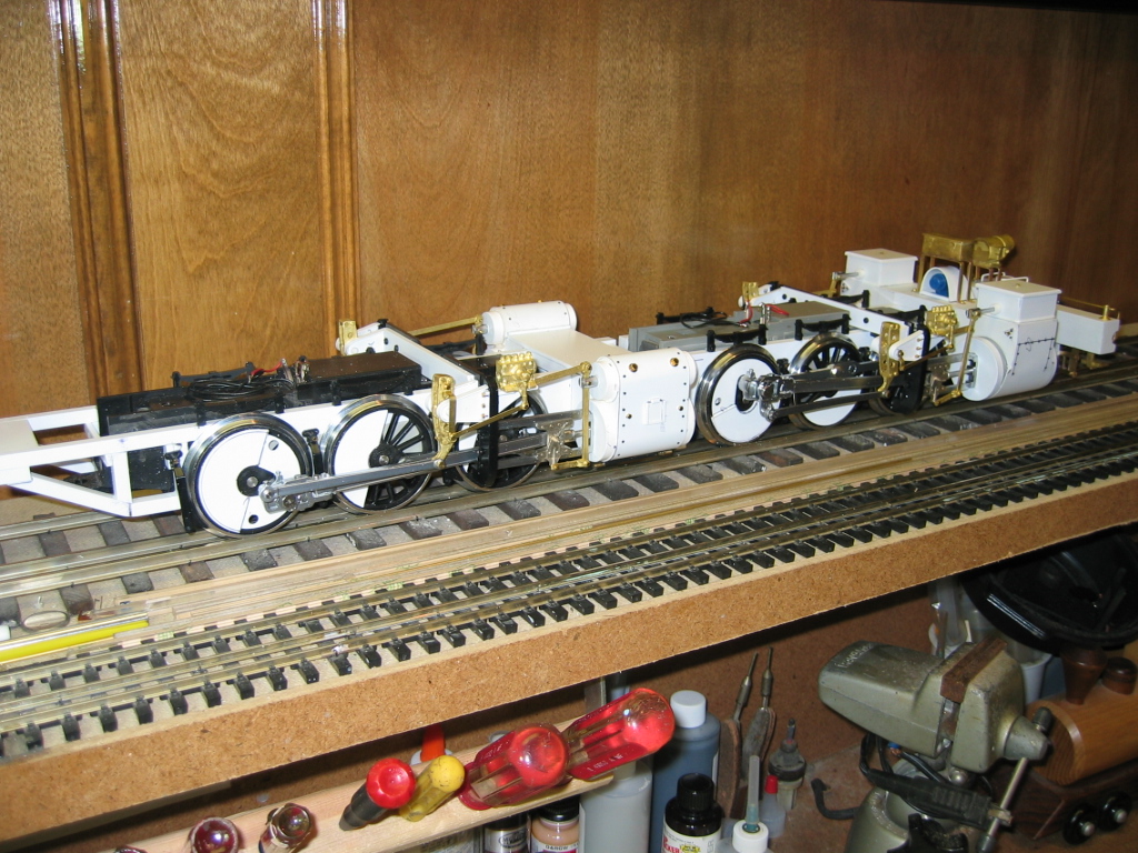
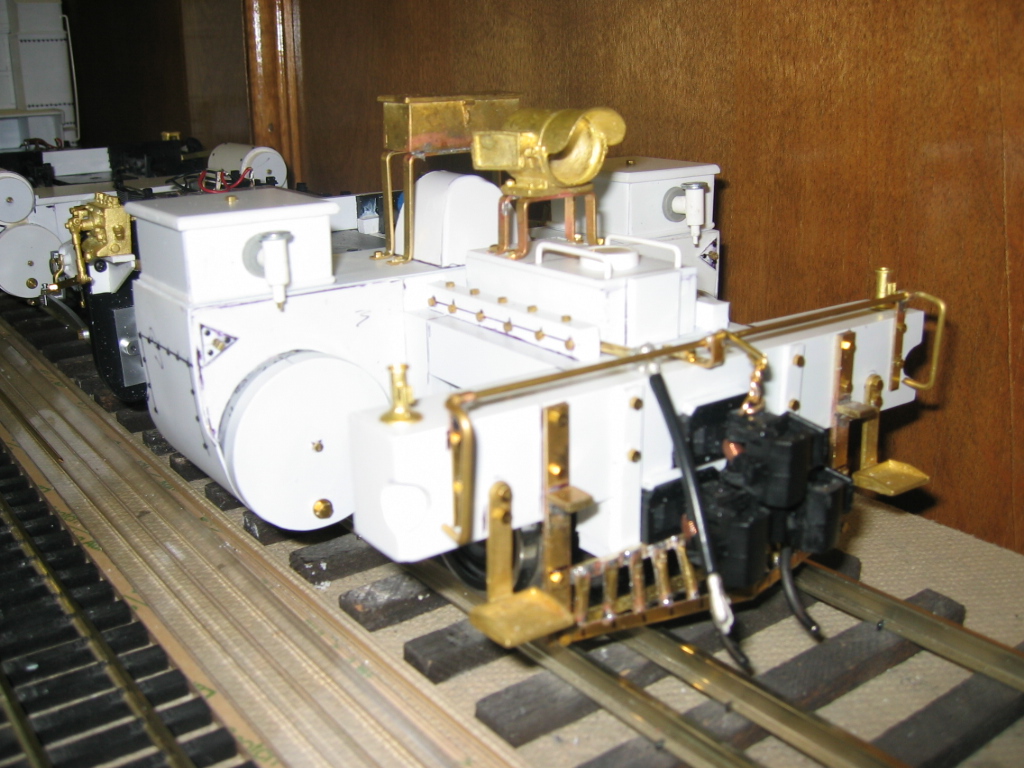
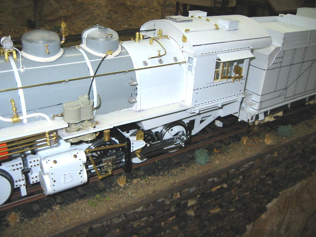
The Boiler &
Cab
The boiler on the
L-131 is a large, 4" diameter length of PVC pipe with a styrene
spacers and a sleeve of styrene sheet added to their circumference
to match the dimensions and taper of the prototype's boiler jacket.
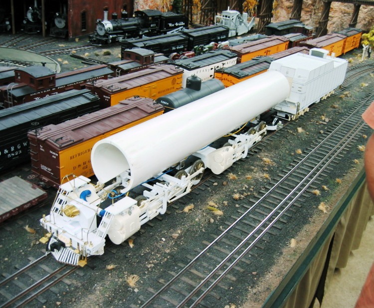
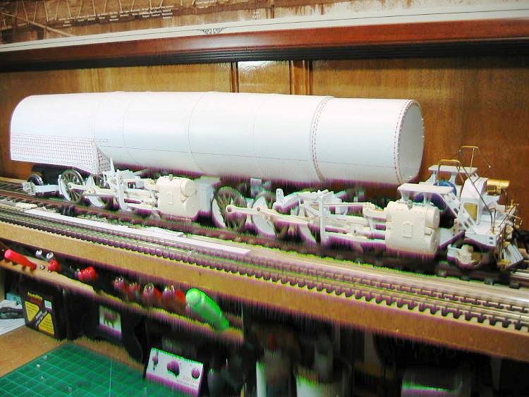
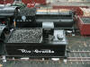
Barry writes,
"The L131 is just big, so big that it is hard
to handle. This will be the first engine that I do not have to
add a metal weight to. Don't ask me how much it weighs, but it
is heavy. the boiler is over a half inch thick at the largest
point. The first pictures show the pipe attached to the engines
on the layout, before I added the taper to it. Later pictures
show how I added the strips to build it up and add the 40 thou
thick jacket sheet to it. I then turned the boiler upside down
and filled it with urethane, to make it solid between the pipe
and the outside 40 thou jacket. The basic boiler is done and the
running boards are going on next, followed by a bunch of foo foo
to make it look good. I added the sound speaker in the fire box
area, so sound will come from the engine, instead of the tender.
I may add an additional speaker in the smoke box area, if I
think it needs it. It has really been a fun project to work on,
and I would like to have it done for the Lone Star Regional
convention here in town, in the middle of June. We will see."
"I brought the engine up to the layout to test the distance from
the tender and engine, as well as check the clearances around
the curves. I thought I would have to do some major revisions to
the scenery, but in only two places do I have to make changes,
to accommodate the cab swing. I was worried about the pivot
points from the engines to the boiler, but they are in the
correct places to clear most all the scenery. Over all, I am
please with how it runs and that I don't have to go back and
make corrections. I am glad this is not my first engine to
build! The hardest part of this engine project is handling it,
or turning it around on the workbench. It is very heavy and
long. I am not sure how I am going to hold the boiler to paint
it."
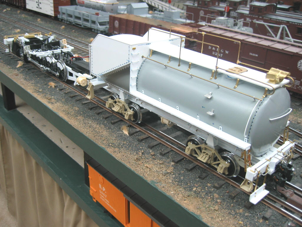
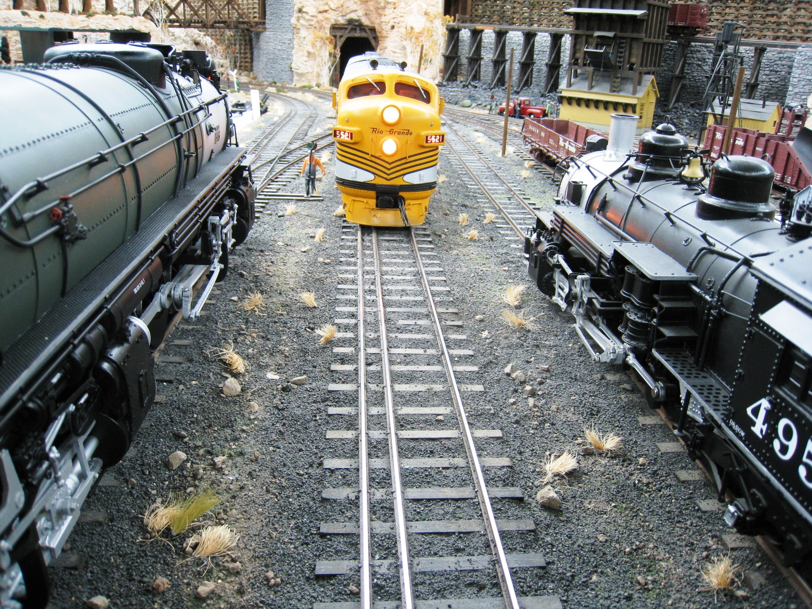
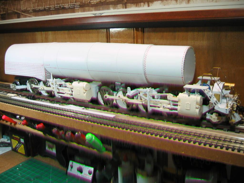
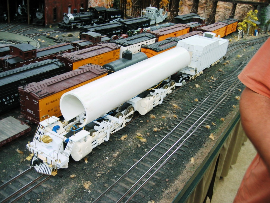
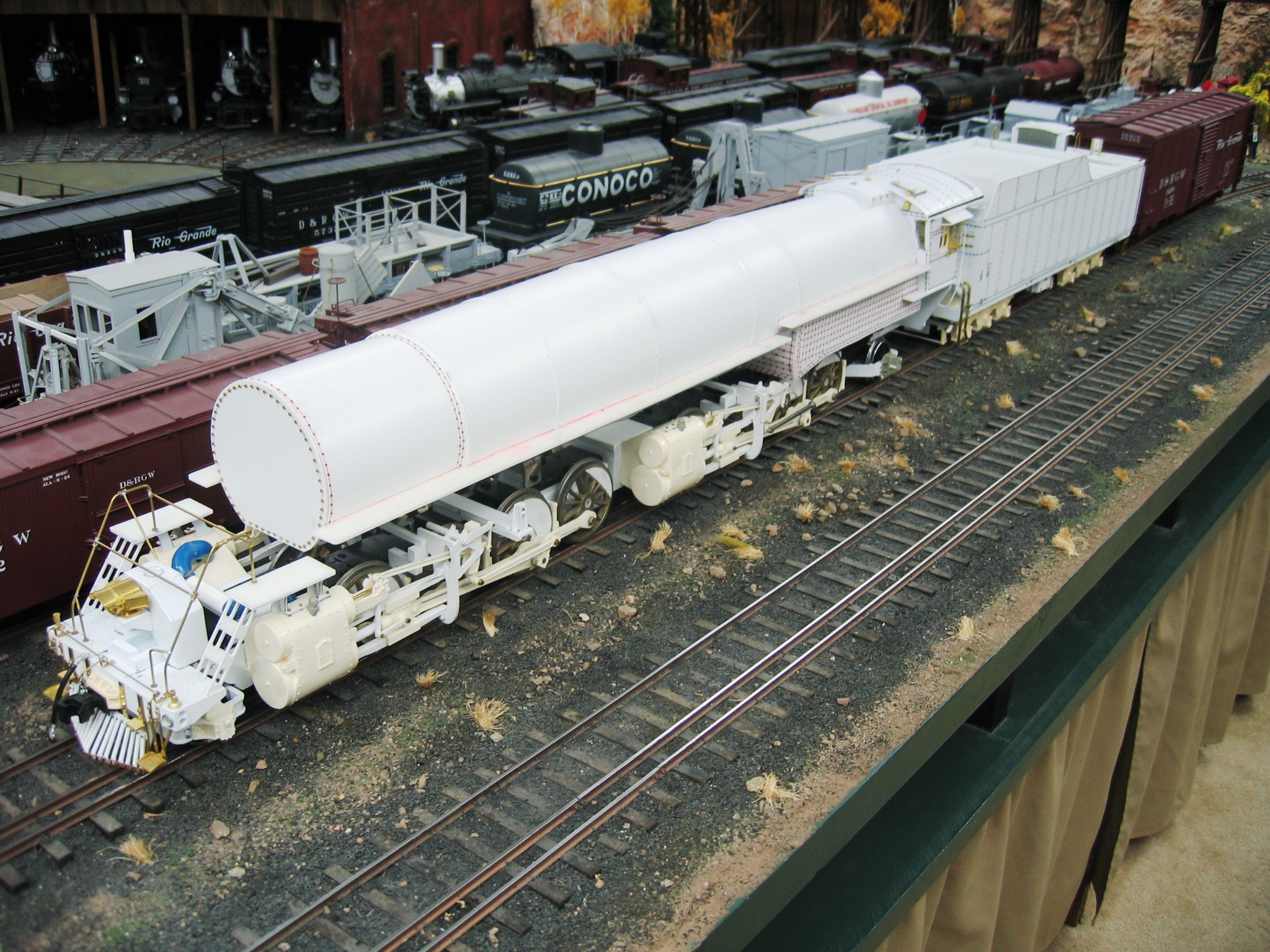
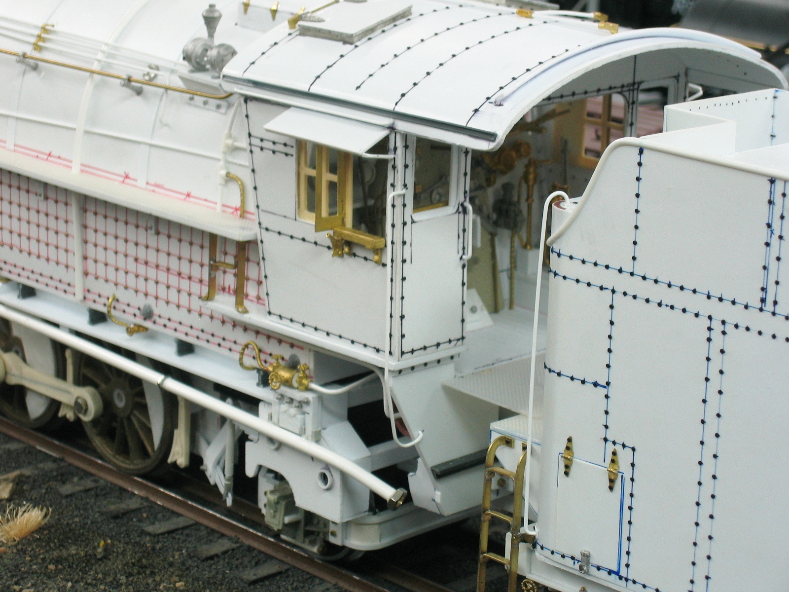
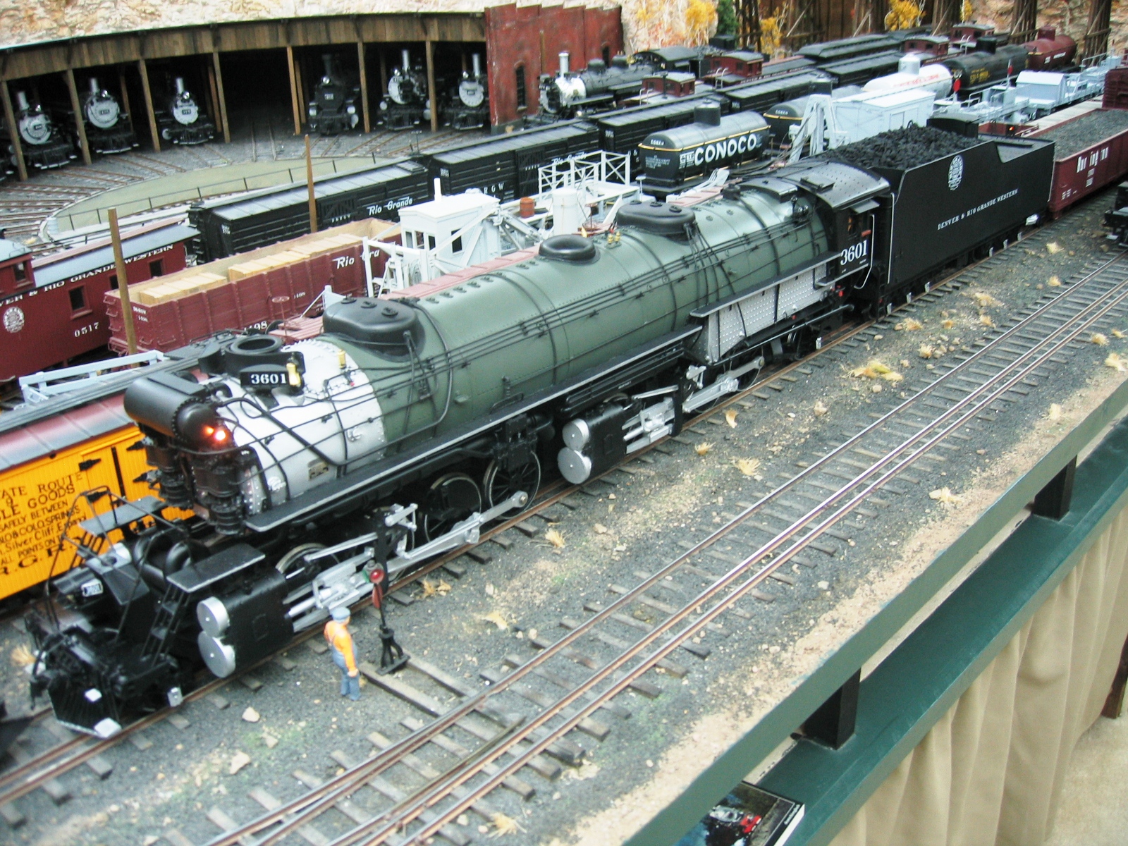
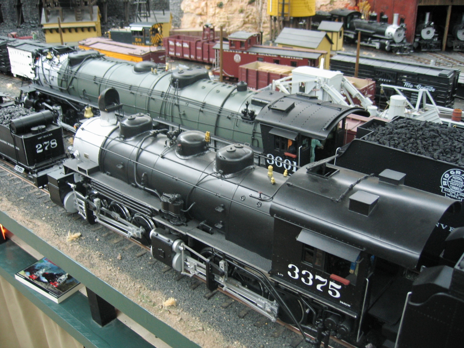
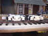
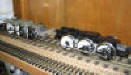
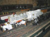
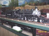
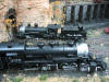
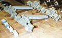
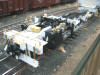
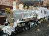
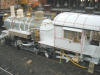
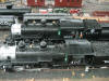
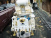
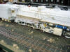
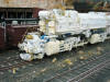
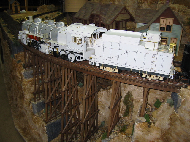
The photos below were taken in
April and May of 2008:

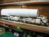

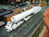

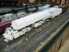


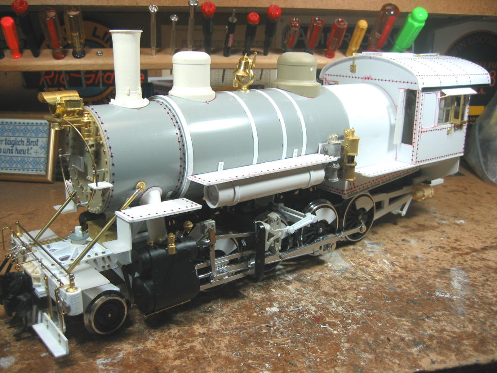
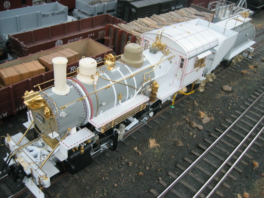
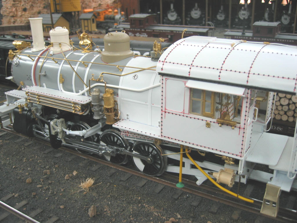
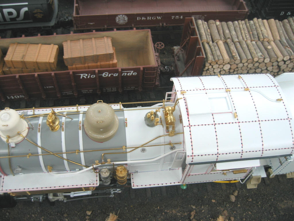
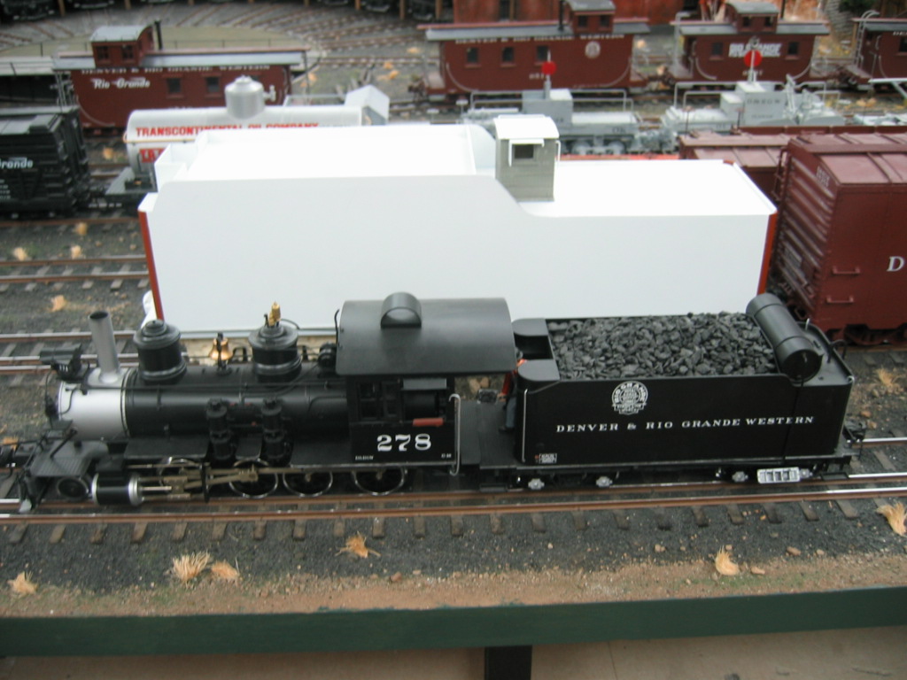
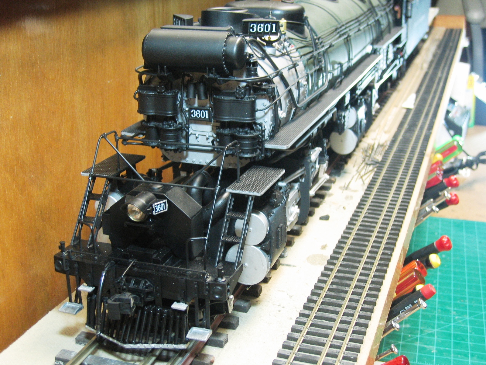
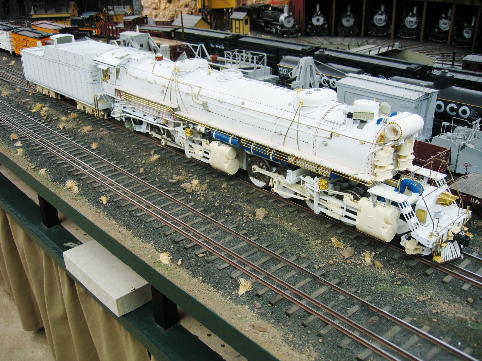
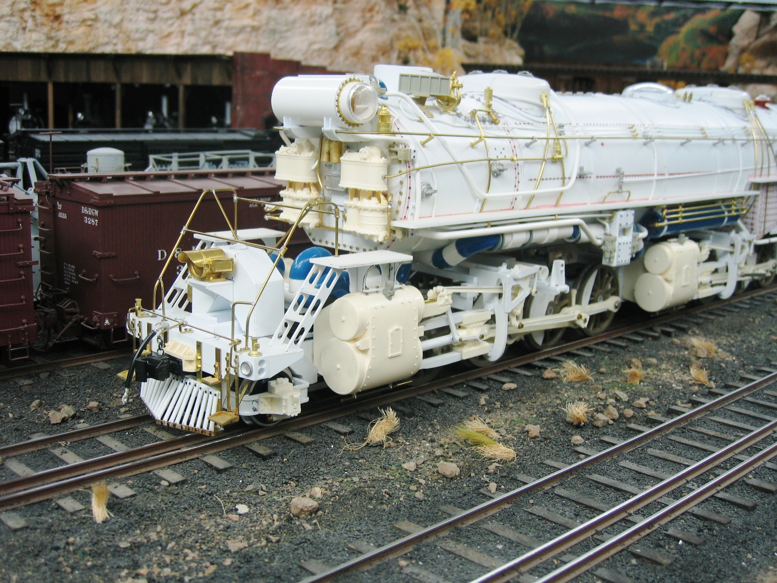
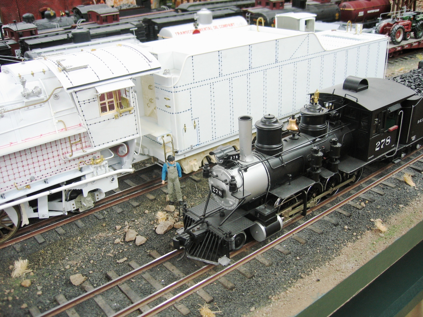
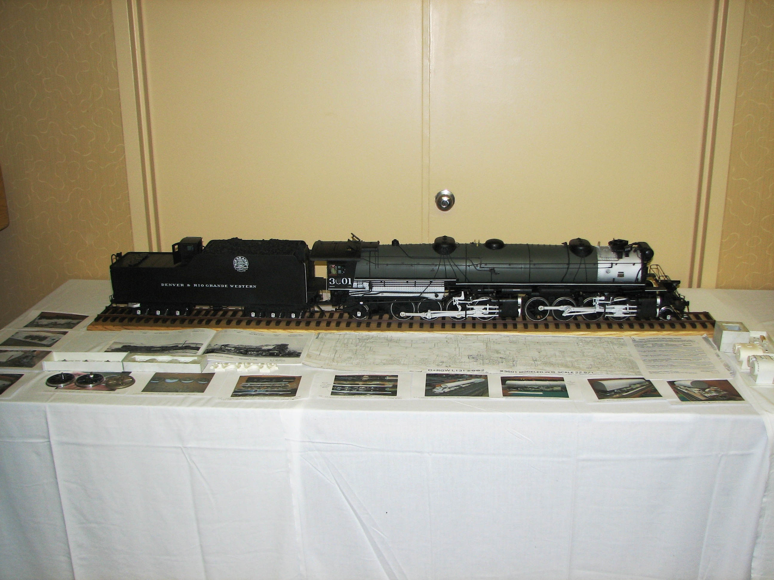
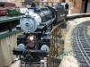
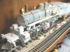
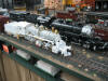
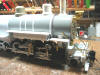
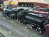
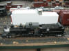
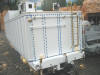
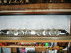
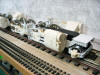
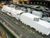
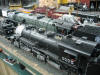
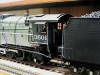
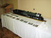
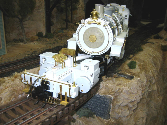
The Completed Locomotive
Without paint . . .(notice the narrow
gauge C-16 in the foreground!)
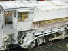
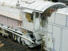


Barry has this to say about the end of
the project:
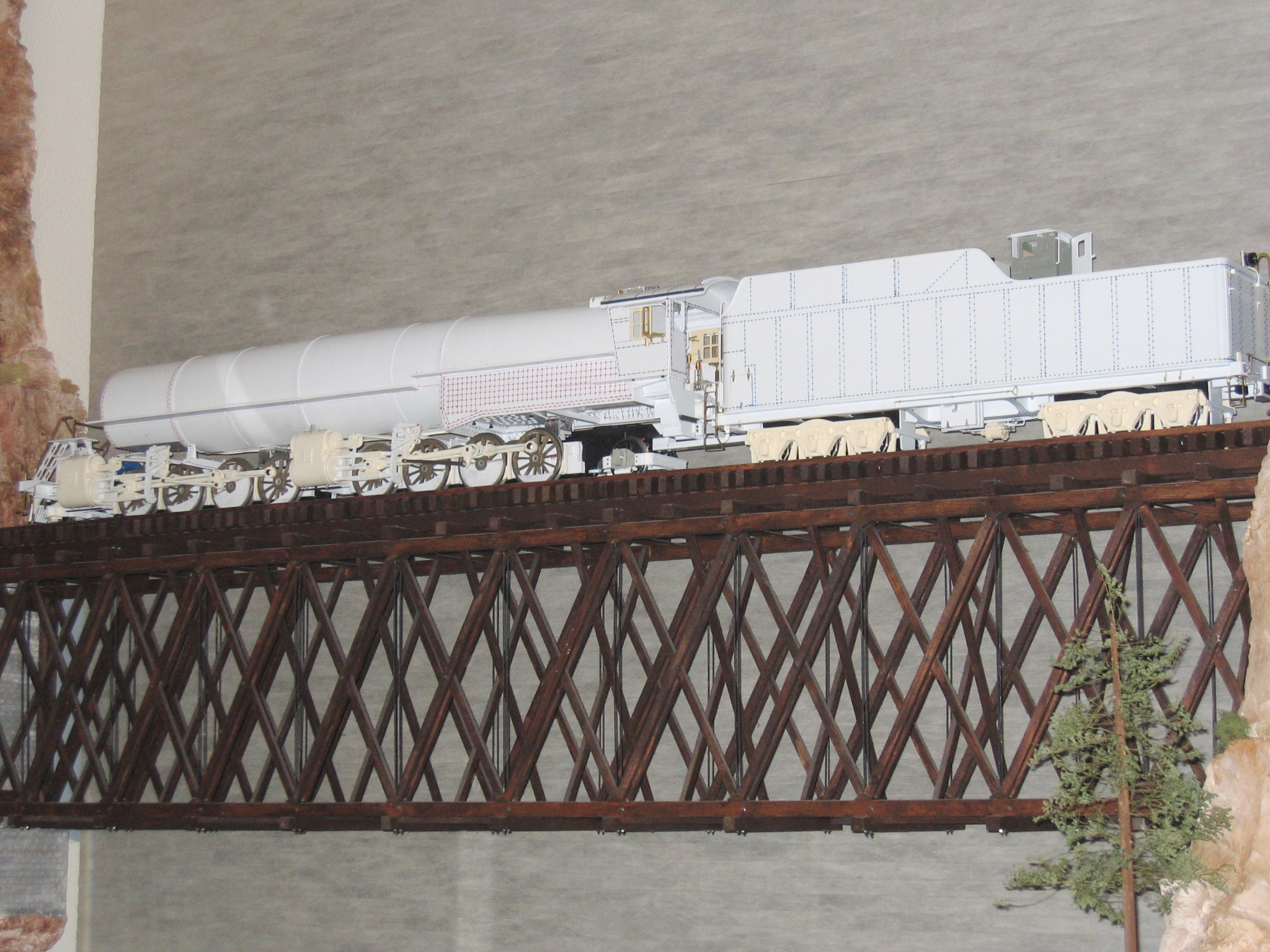
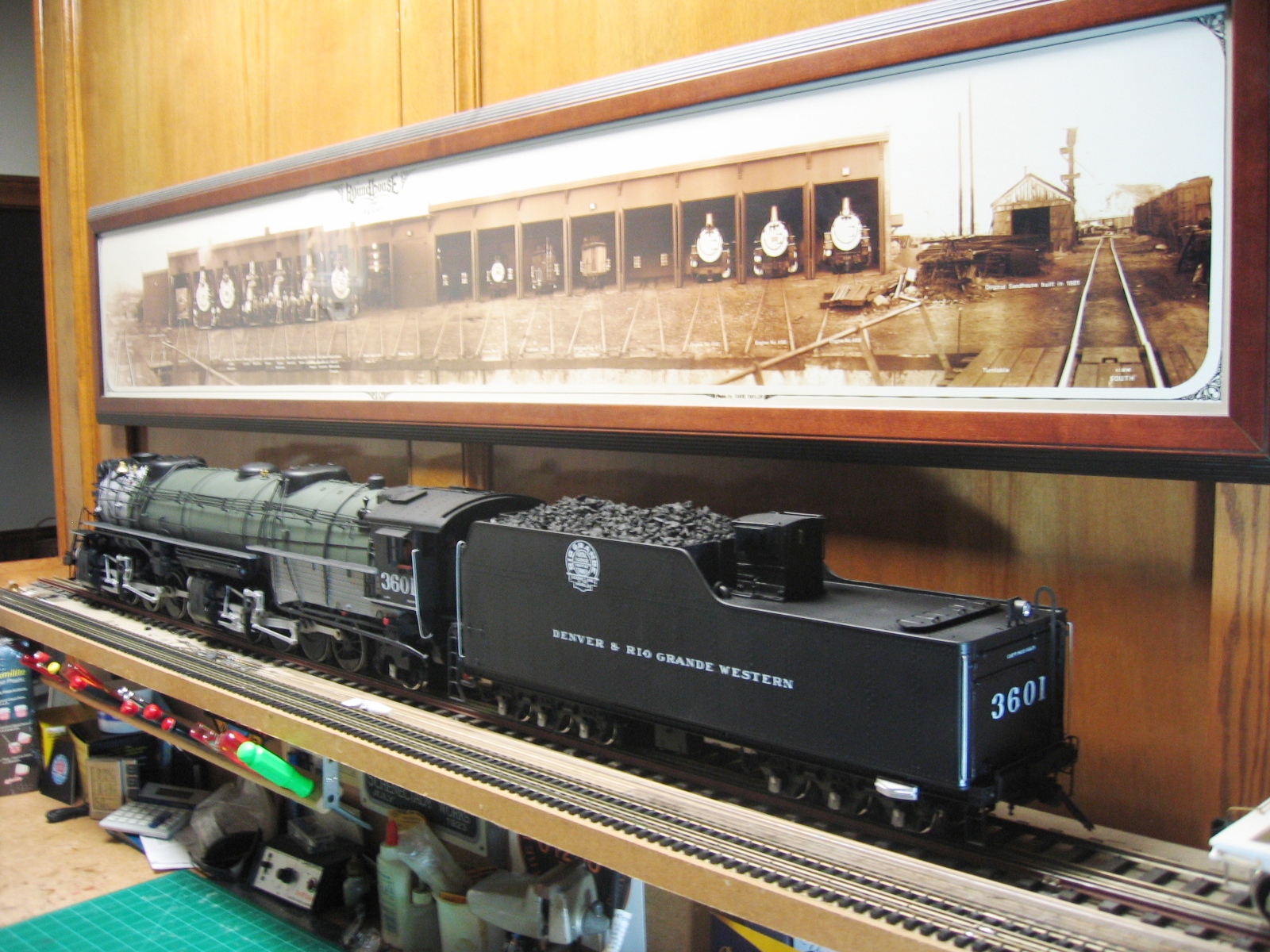
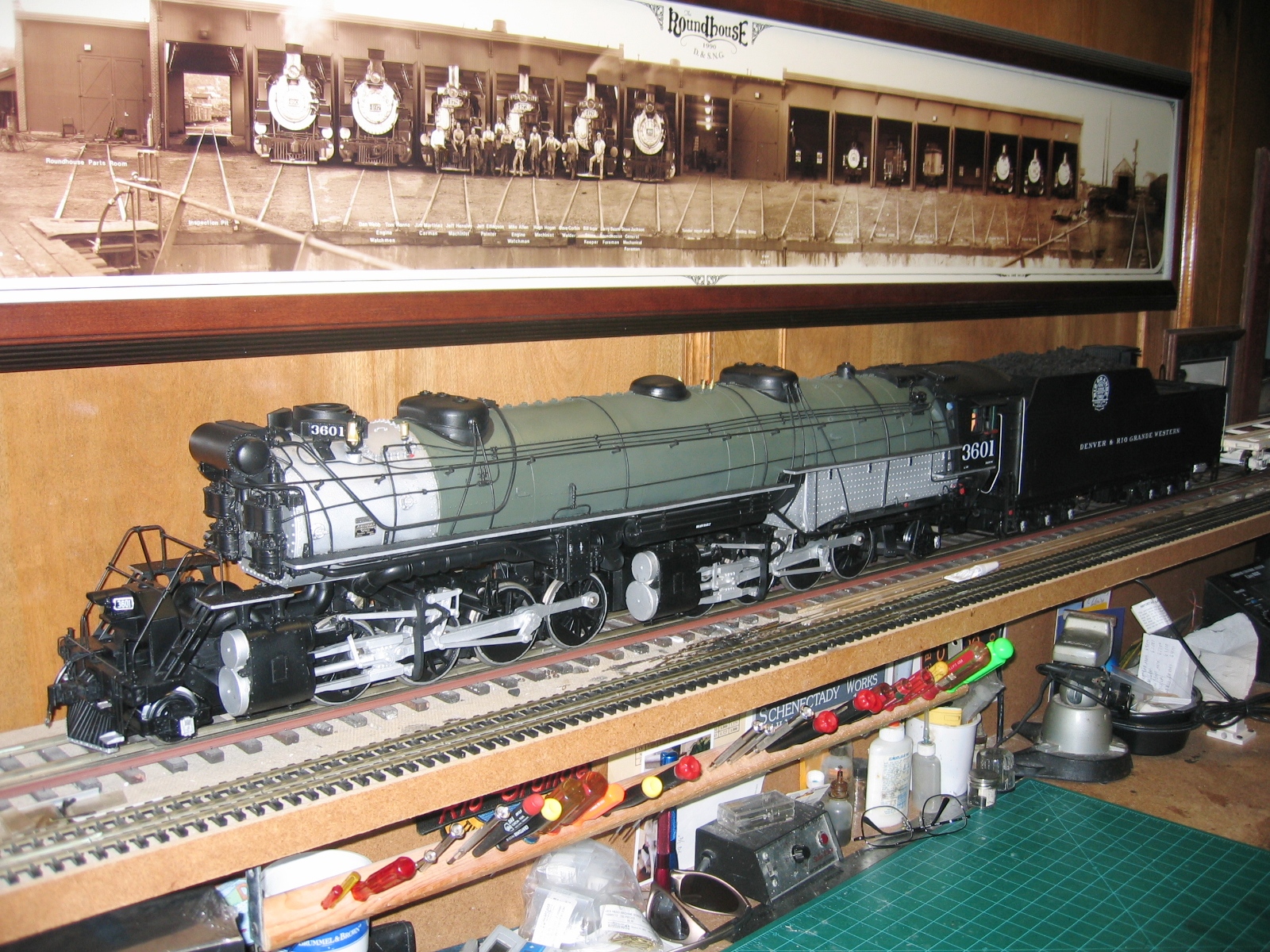
|
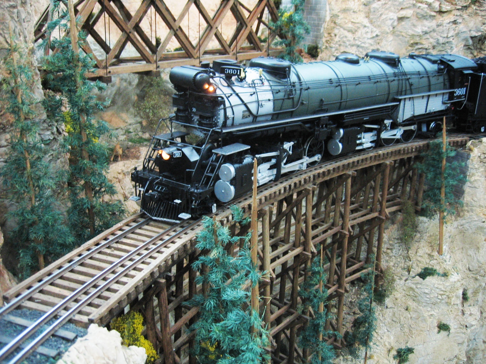
"The BLW shop crew has been very busy and
finally got the L131 out the door and ready for the paint
shop. All the foo foo is just about on it now and they have
decided to call it a "Choo Choo". It is the largest piece of
rolling stock that I have built, at 65 inches coupler to
coupler, 9 inches high and 6 inches wide. Of course it runs
on my five foot radius track and looks funny doing it, but
hey, it's what I wanted. I have a little more work to do on
the engines once I remove them from the boiler, and ready it
for wiring and sound. The engine is very heavy and I don't
always know where to lift it from. I will be glad when it is
on the layout to stay. Over all, I am pleased with how it
turned out. There were very few revisions to get it to run
and all the planning and homework paid off. Would I build
something this large again? Well..... yes from the fact
that I really enjoy large locomotives, no from the fact it
is so hard to handle and it takes up so much space. (I would
probably say yes, if you really want to know)"
"I want to say a big thanks to all who have helped me with
this project. Dave Brown for all the great pictures of his
PSC L132 O scale engine, Mark Gardner for the plans from the
Colorado Railroad Museum and the pictures of his PSC L131 O
scale engine, Craig Brantley for loaning me his O scale Max
Gray L131 engine and reducing the plans for me, Ward Hammond
for all the laser work, James Engle for the custom decals,
yet to go on, Jonathan Meador at LGB of America for help
with all the drive parts, and Dennis and Kathy Mashburn who
cast all the drivers and Dennis who machined the centers for
me.Without help from good friends, I
would not be able to build what I do. Thanks Guys!"
"I was asked what I will do to top this project? Well, nothing
soon, but I like large engines and a Big Boy has always been
a favorite of mine." |
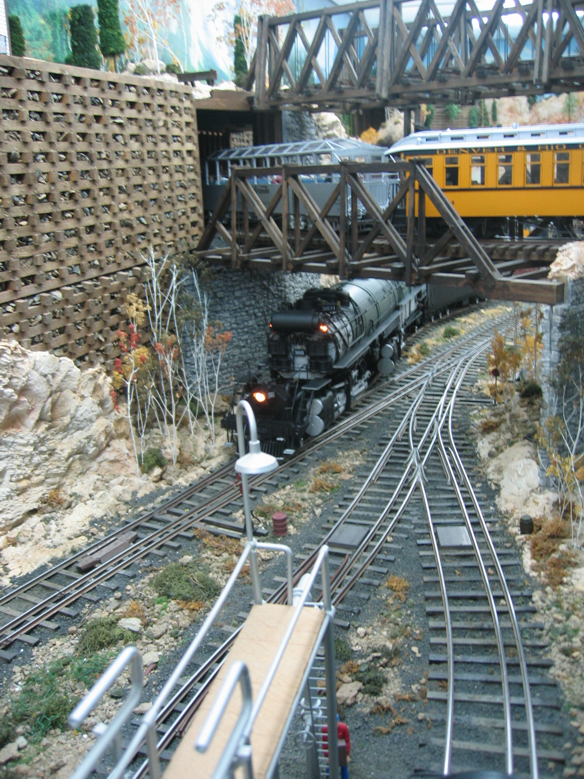
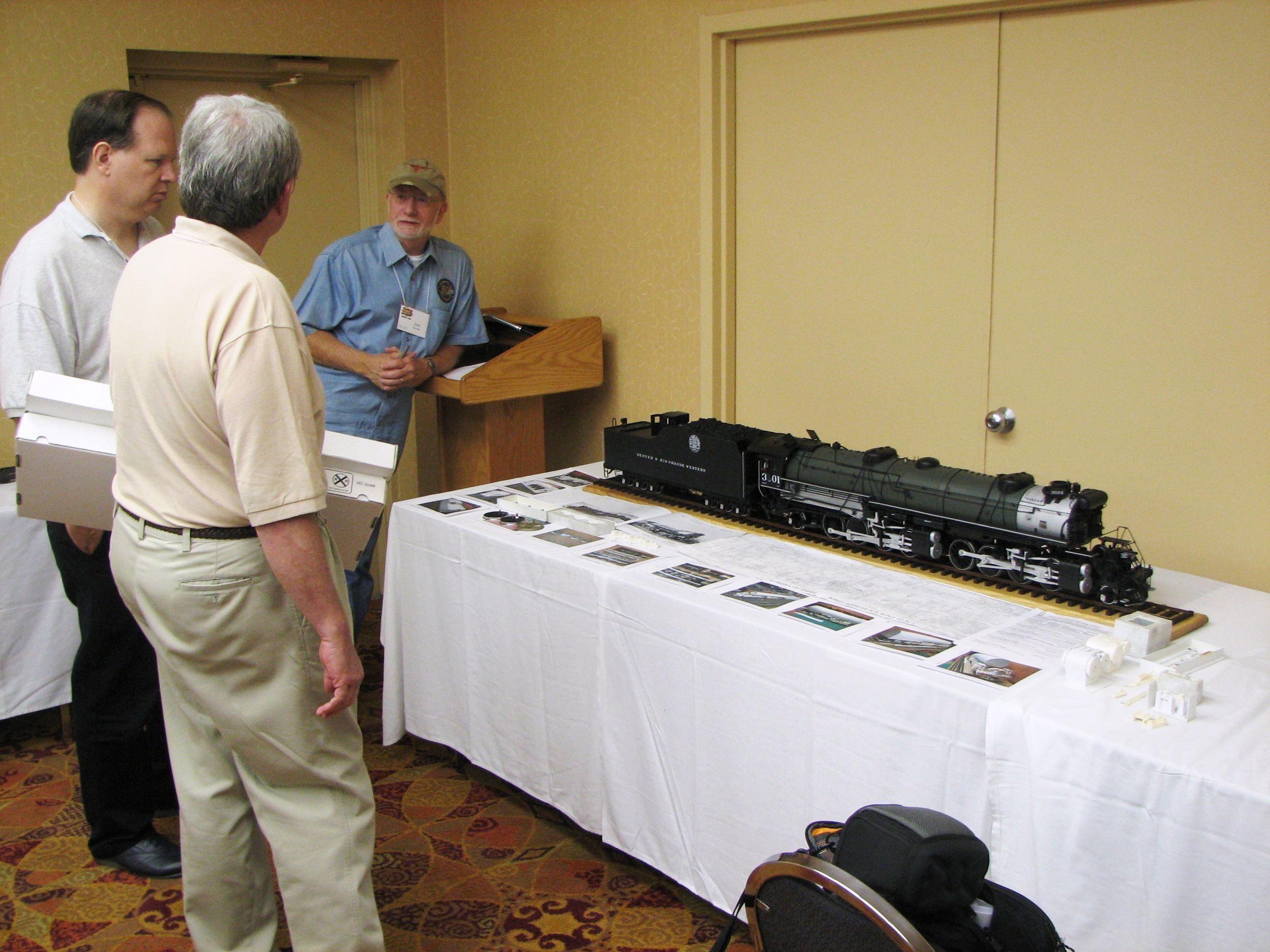
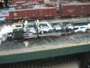
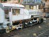
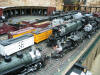
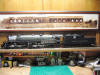
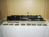
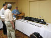
Painted and lettered . . .(And in the
last set of frames at the 2008 Lone Star NMRA Convention)


 |
|
Last update: 20 January 2009

|
.JPG)
.JPG)


.jpg)
.jpg)


.JPG)


.JPG)
.JPG)

.JPG)
.JPG)
.JPG)
.JPG)
.JPG)
.JPG)