.JPG)  |
|
"Your source for standard gauge modeling in 1:20.3" |
|
|
|
|
||||||||||
|
During the summer of 2013 I was approached by Jonathan Meador, sales manger for PIKO America, whom I had met several years before at my friend Barry Bogs' home in Houston while Jonathan was exhibiting PIKO products at a Houston area World's Greatest Hobby Show. PIKO has been expanding its lineup of America prototype freight cars and locomotives since it entered into the "G" scale train market beyond its well-known product line of injection molded, outdoor building kits. Jonathan had kept tabs on my work as it has been chronicled on this website and had seen my scratch built 40' fish-belly flat cars, built in both 1:22.3 scale, Gauge 3 as well as 1:20.3 scale, F Gauge. Jonathan asked if I could build a roughly 1:29 version of my flat car as a pilot model for a PIKO America injection molded version of the same. The pilot model was built without most detail parts, the intent being to get a "sizing" model to compare with other rolling stock in the PIKO product line. The two sizing models were made differently from my Gauge 3 and F scale models. Instead of using Plastruct ABS channels and hand-cut sheets of styrene for the center sills, the PIKO sizing models were first drawn in AutoCAD and designed to snap together using tabs and slots. These were then cut from styrene sheet using our laser cutter and then glued together. A feel brass parts were added along with a couple of PIKO injection molded trucks. Here are a few pics of the process and then the results:
Below are pics of my Gauge 3 original, built in 2001, with the unpainted PIKO sizing model at right, made in September of 2013. The accompanying boxcar was originally part of the Model Die Casting product line, now reissued by PIKO America. As you can see, the sizing flat is roughly the same length and width as the 40' MDC / PIKO boxcar. |
||||||||||
|
|
||||||||||
|
|
||||||||||
   Customer
Photos of Boxcar Kits
(News from 2014 updated 4-15-15) Customer
Photos of Boxcar Kits
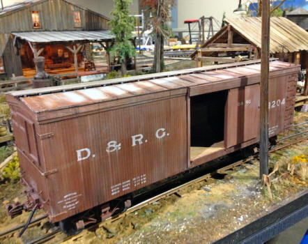
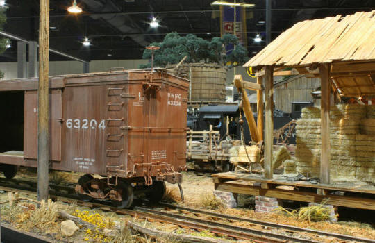
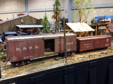
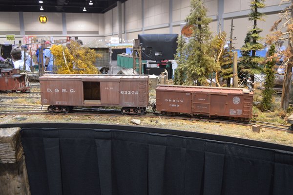
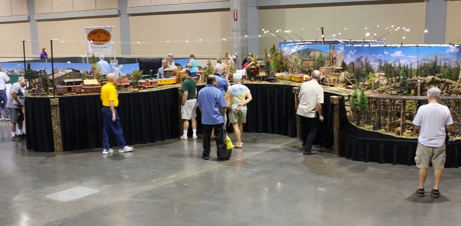
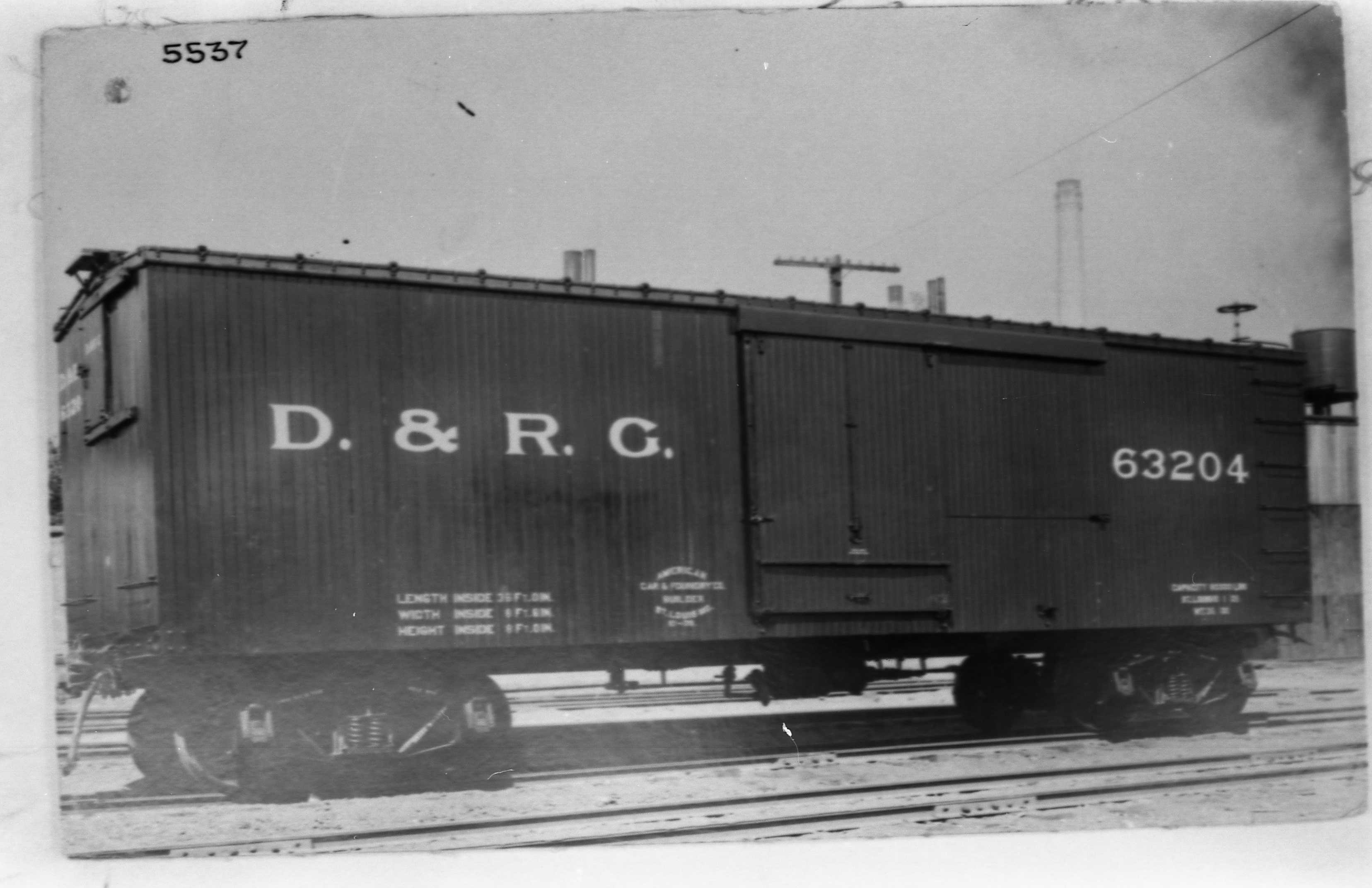
(News from 2014 updated 4-15-15)As of the end of 2014, about 18 of our 36' boxcar kits have been sold to several different individuals, including two that have gone to the Sundance Central modular model railroad on permanent display just a few miles north of Tampa, Florida. Sundance member Frank Palmer did a spectacular job of modifying one of our Southern Railway 30 ton boxcars to mimic a steel underframe D&RG car built at about the same time period. Frank added a metal roof and lettering produced by Stan Cedarleaf from both photos and stencils of the 100 year old D&RG car. Frank also created a blog with photos showing the building of his car and discussing his weathering techniques. You can view it here. The car occupies a dual gauge spur added in mid-2014 to the engine servicing peninsula on the Sundance layout.
|
||||||||||
.jpg) .jpg) Making
Tracks
(News from 2014 updated 4-15-15) Making
Tracks
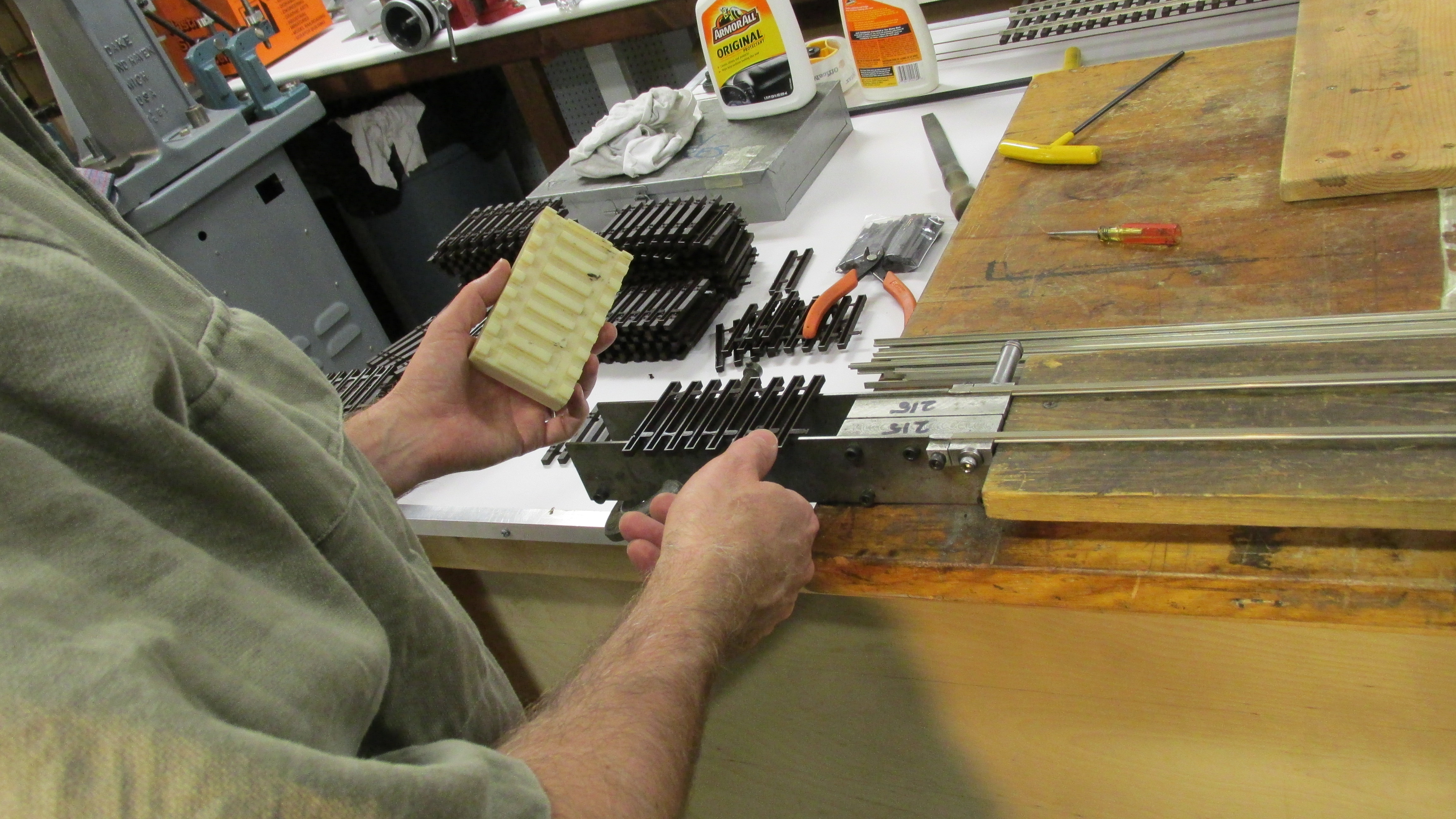
(News from 2014 updated 4-15-15)Since introducing assembled flex track this past year (2013) it has been a please to see orders for both F Gauge and Dual Gauge track take off. Prior to making my first laser cut track assembly jig, assembling the tie track to rail was pretty well limited to pushing about 2-3 ties at a time up a section of rail. Now that time has been drastically cut, and an entire 6' panel of track can be assembled in just minutes. One of our customers in Colorado, Mr. Paul Persichetti, is assembling what will no doubt be the largest F & Fn3 outdoor dual gauge railroad in the country--all from CME dual gauge tie strip using Llagas code 250 aluminum rail. Way to go Paul! As of May 2014 a new batch of three-point track gages have also been made using our Milltronics cnc machining center. Something new is the Gauge 1 / Fn3 track gage we now make and offer through our own shop as well as our friends at Llagas Creek. If they run out, we'll make more. Cumberland track is now being shipped ten sections to a box, or bundled with other boxes of track. For those who prefer, we can still ship track unassembled as tie strip and an accompanying 75" long tube of rail.
|
||||||||||
.jpg) .JPG) The
Llagas Creek Interlude
(News from 2014 updated 4-14-15) The
Llagas Creek Interlude
(News from 2014 updated 4-14-15)For better than 20 years one of the independent suppliers of Gauge 1 track has been Llagas Creek Railways. Founded by Gary Broeder in the late 1980s, Llagas started out with Gary working in his garage assembling flex track from a two-tie plastic tie strip, made in a pint-sized small injection mold originally built by Cliff Grandt, and custom building hand-made turnouts with wood ties. In the next few years, as demand picked up for Gary's more realistic, scale-conscious tie strip (as opposed to the monstrous toy tie strip offered by LGB), a total of three different tie strips were marketed by Gary and Llagas. The molds for these tie strips were either built or out-sourced by Baltimore-area plastics company Space Ltd. and its owner Bill Mai (see mold pic at bottom right). Turnout production shifted to a talented ex-military veteran turned "prepper", Mr. Tom King (pictured at right, seated) who worked out of a shipping container, off-grid, located somewhere on a central California hillside. Gary sold Llagas to Bill Mai in about 2006. Initially production levels and sales continued to increase. As Bill Mai approached his 81st birthday in 2013, however, and Tom King went through a series of health crises, it became apparent that new blood was needed. That's where I came into the story.
|
||||||||||
|
Llagas survives--sort of--with Jerry Hyde of Hyde Out Mountain Live Steam in eastern Ohio (pictured above right with me) assembling track, Bill Mai ostensibly taking orders in Florida, and one other person hand building the turnouts. Even Gary Broeder has gotten back into building a few of the turnouts. Tom King, I am sorry to report, has been in hospice care due to the return of his cancer. |
||||||||||
.jpg) CNC
Milling Bettendorf Sideframes
(updated 1-22-14) CNC
Milling Bettendorf Sideframes
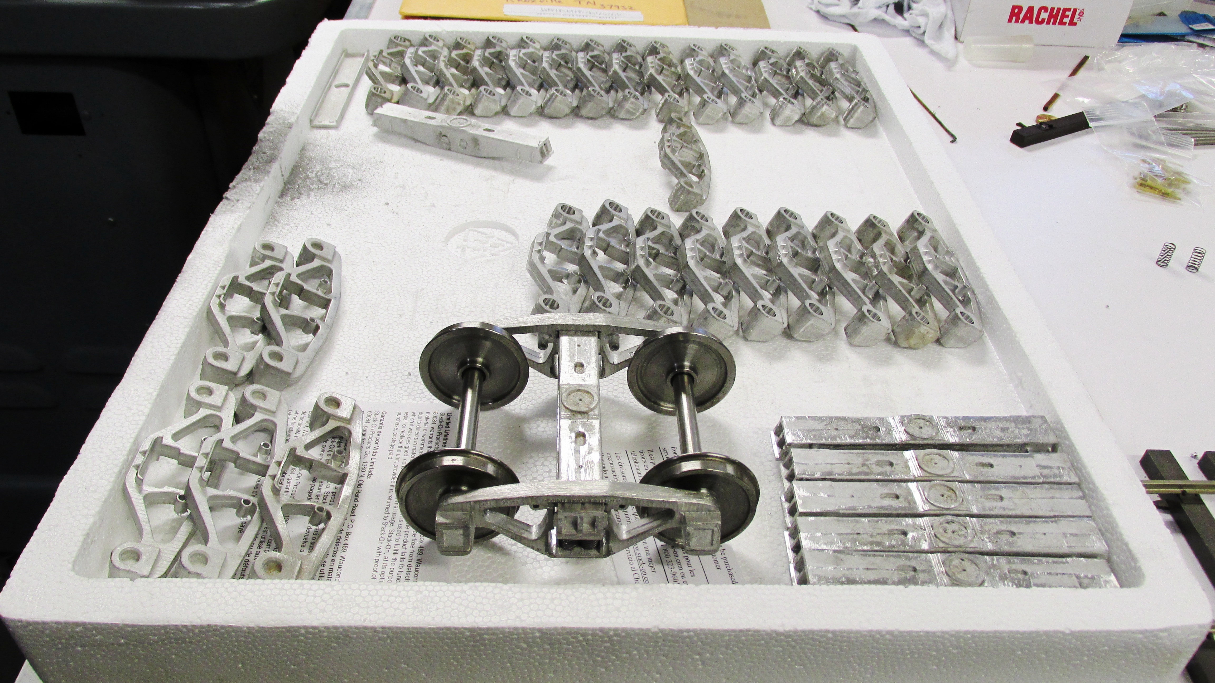
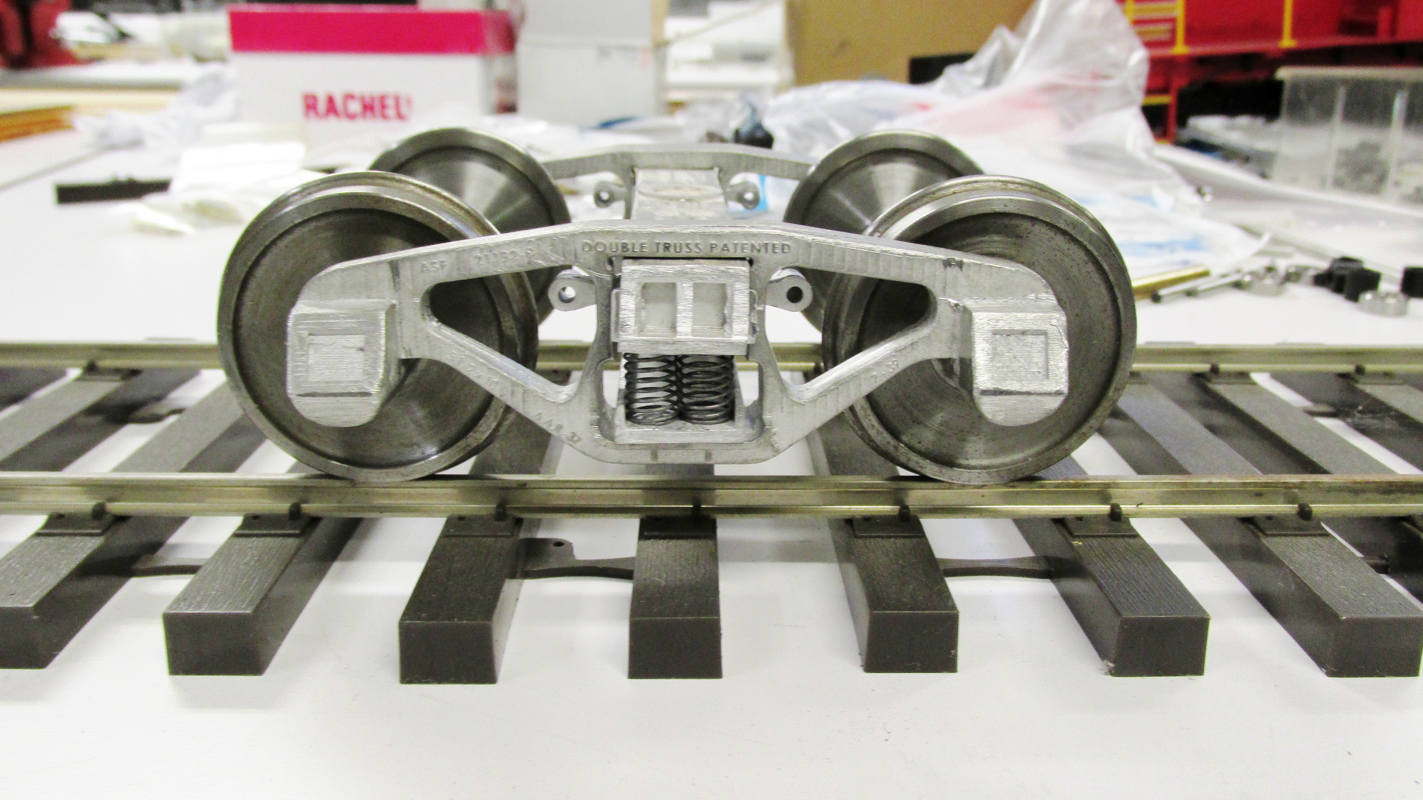
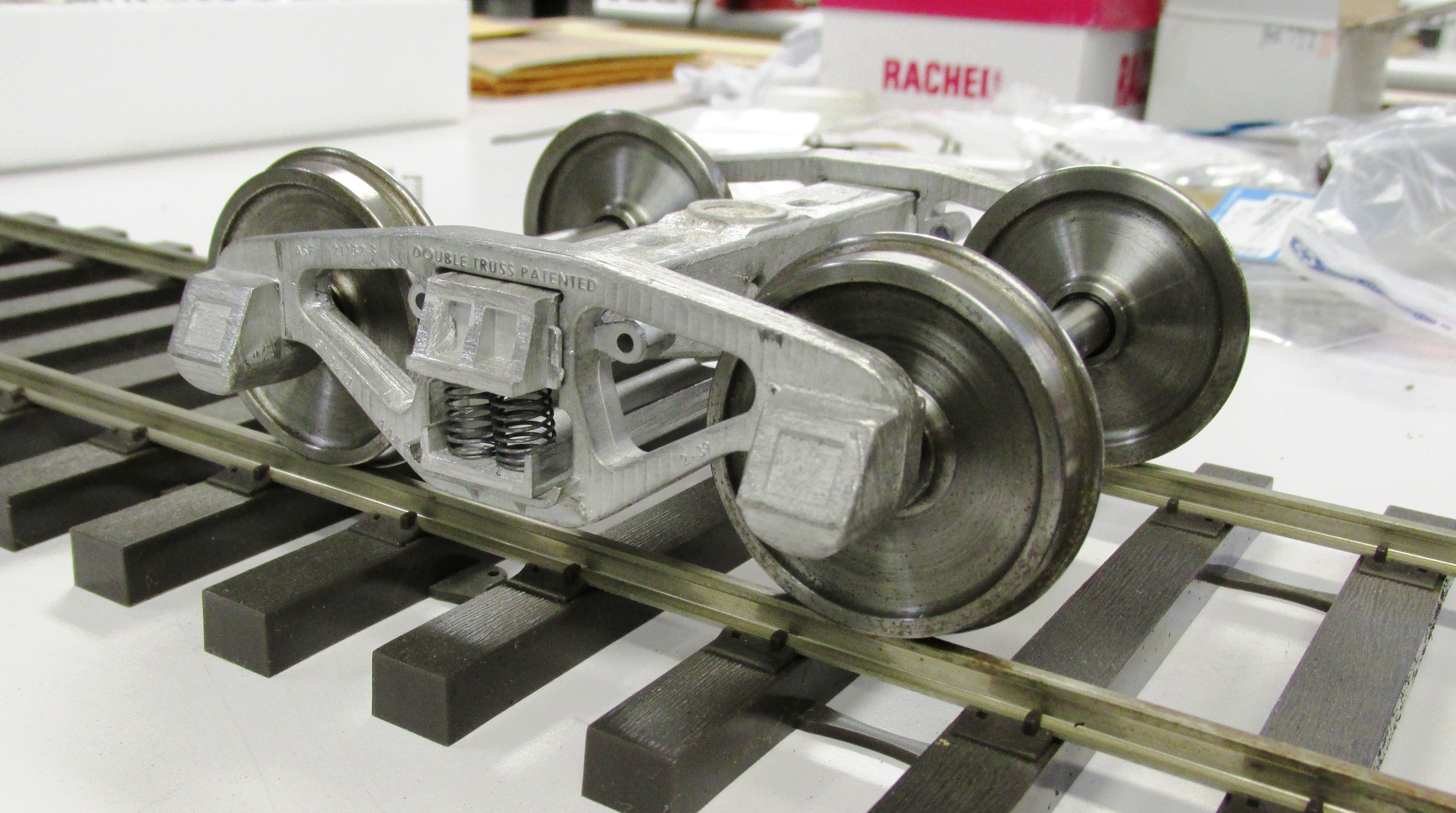
(updated 1-22-14)Finally after many years of preparation and acquiring of equipment, we are mass-producing freight car trucks in 1:20.3 standard gauge. Here are a few pics--and a video--of Bettendorf trucks being assembled by my friend Don Niday in my shop. Don has been casting the truck parts on our own spin casting equipment and has been drilling and counter-boring them on my cnc mill. Young Jonathan, my almost 4 year-old boy, helps out with pressing ball bearings into place. Knock'em home, Jonathan!
Trucks are available direct from Don at (865) 671-1270 or view the Truck Products page. |
(Drilling & Counter-boring Truck Sideframes-January 2014) |
|||||||||
    CME
in the Press
(updated 1-7-14) CME
in the Press
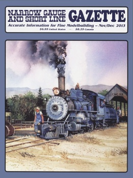
(updated 1-7-14)Four of the model railroad trade publications have honored Cumberland Model Engineering with either Products Reviews or Product Announcements over the last couple of months. In particular we would like to thank
It is thanks to trade publications such as these that our hobby and the wide spread availability of products and information exist. Electronic media is certainly a delightful additional to print, but in my opinion, no electronic medium will ever replace the visceral experience of reading a good book late at night, waiting for the next issue to arrive in the mail, or seeing what others are building with a simple flip of the page while in the "library." At CME we patronize these publications and their other advertisers. We hope you will too. |
||||||||||
.jpg) .jpg) Freight
Car Trucks Available
(updated 1-7-14) Freight
Car Trucks Available
(updated 1-7-14)Finally after what seems like years of delay, the first standard gauge freight car trucks are available in F scale. These include a wooden bolster archbar truck of the 1890s, based upon a Pullman prototype, and the ubiquitous 50 Ton AAR-Bettendorf truck, in this case, based upon the Norfolk & Western T-64 class truck cast by Buckeye and others. Each truck includes double insulated steel wheels and is ball bearing equipped. Trucks come as semi-kits requiring just a bit of assembly and clean up of the white metal castings--just enough to keep you off the streets and out of trouble for at least one night. For more information, as well as directions for ordering, please see our Truck Products page. |
||||||||||
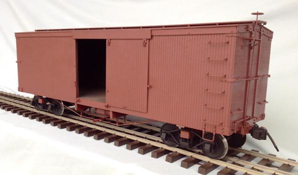 SR
30 Ton / 36' Boxcar Kit Nears Completion
(updated 1-7-14) SR
30 Ton / 36' Boxcar Kit Nears Completion
(updated 1-7-14)Cumberland Model Engineering is very pleased to announce that our first-ever boxcar kit is nearly completion, pending the arrival of a batch of brass detail part master patterns from upstart "factory of the future" Shapeways. Three more advance or beta kits have gone out and it is looks like the end of January will finally bring the first ten of these kits to completion. Everything which an experienced kit-builder would want is here, but with a few extra goodies, including brass grab irons and stirrup steps inspired by my friend Phil Dippel of Phil's Narrow Gauge, interior bracing and lading walls as typified by John Clark's excellent Fall River Productions Carter Brothers Fn3 kits, and Bob Hartford's flare for exceptionally well-detailed museum quality kits, with lots of drawings and overviews. In addition, dry transfers based upon the actual Southern Railway stencils of 100 years ago are on their way from Tom Dempsey at Clover House, and each kit has a CD-ROM of prototype photos, along with pics of the first couple of test builds. I owe a good deal of thanks to several individuals who have made the creation of these kits possible, namely
And lastly, you the customers are the ones making this possible. Without you, there would be little reason for, nor support of, standard gauge modeling in 1:20.3 |
||||||||||
| Continue to CME News 2013 . . . | ||||||||||
|
Last update: 14 April 2015
| ||||||||||
.jpg)
%20030.jpg)
%20010.jpg)
%20003.jpg)
%20014.jpg)
%20001.jpg)
%20008.jpg)
%20019.jpg)
%20029.jpg)
%20009.jpg)
%20016.jpg)
.jpg)
%20007a.jpg)
%20008a.jpg)
%20034a.jpg)
%20019a.jpg)
.jpg)
.jpg)
.jpg)
%20038(350).jpg)